ELCO S.r.l. - ELK 38 - OPERATING INSTRUCTIONS - Vr. 02 - ISTR 06261 - PAG. 9
4.11 - LOOP BREAK ALARM FUNCTION
All the parameters referring to the Loop Break alarm function are
contained in the group “
]
LbA”.
The Loop Break alarm is available on all the instruments, which
intervenes when, for any reason (short-circuit of a thermocouple,
thermocouple inversion, load interruption), the loop control is
interrupted.
First of all, it is necessary to establish to which output the alarm has
to correspond.
To do this it is necessary to set the parameter relative to the output
to be used (“O1F” , “O2F”) in the group “
]
Out”, programming the
parameter as :
= ALno if the alarm output has to be ON when the alarm is active
while it is OFF when the alarm is not active.
= ALnc if the alarm output has to be ON when the alarm is not
active while it is OFF when the alarm is active.
= ALni if the alarm output has to be ON when the alarm is not
active, while it is OFF when the alarm is active but with reverse led
indication (led ON= alarm OFF).
Enter group “
]
LbA” and program which output the alarm signal has
to be addressed to on par. “OLbA”,.
The Loop Break alarm is activated if the output power remains at
the 100% of the value for the time programmed on par. "LbAt"
(expressed in sec.).
To avoid false alarms, the value of this parameter has to be set
considering the time the plant takes to reach the Set point when the
measured value is a long distance from it (for example at the plant
start-up).
On alarm intervention, the instrument visualizes the message
“LbA” and behaves as in the case of a measurement error giving a
power output as programmed on par. “OPE” (programmable in the
group “
]
InP”).
To restore normal functioning after the alarm, select the control
mode “OFF” and then re-program the automatic control (“rEG”) after
checking the correct functioning of probe and actuator.
To exclude the Loop Break alarm, set “OLbA” = OFF.
4.12 - FUNCTIONING OF KEY “U”
The function of key “U” can be set through par. “USrb” contained in
the group ““
]
PAn”.
The parameter can be programmed as :
= noF : no function
= tunE : Pushing the key for 1 sec. at least, it is possible to
activate/deactivate Auto-tuning or Self-tuning
= OPLO : Pushing the key for 1 sec. at least, it is possible to swap
from automatic control (rEG) to manual one (OPLO) and vice versa.
= Aac : Pushing the key for 1 sec. at least, it is possible to
acknowledge the alarm. (see par. 4.10.1)
= ASi : Pushing the key for 1 sec. at least, it is possible to
acknowledge an active alarm (see par. 4.10.1)
= CHSP : Pushing the key for 1 sec. at least, it is possible to select
one of the 4 pre-programmed Set Points on rotation.
= OFF : Pushing the key for 1 sec. at least, it is possible to swap
from automatic control (rEG) to OFF control (OFF) and vice versa.
4.13 - PARAMETERS CONFIGURATION BY “KEY01”
The instrument is equipped with a connector that allows the transfer
from and toward the instrument of the functioning parameters
through the device ELCO KEY01 with 5 poles connector.
This device it’s mainly useable for the serial programming of the
instruments which need to have the same parameters configuration
or to keep a copy of the programming of an instrument and allow its
rapid retransmission.
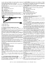
To use the device KEY01 it’s necessary that the device or
instrument are being supplied.
Instrument supplied and device not supplied
Instrument supplied from the device
To transfer the configuration of an instrument into the device
(UPLOAD) it is necessary to proceed in the following way:
1) position both dip switch of KEY 01 in the OFF mode.
2) connect the device to the instrument ELK plugging the special
connector.
3) verify that the instrument or the device are supplied
4) observe the indication led on the device KEY 01: if it results
green this means that a configuration is already loaded on the
device while if it results green blinking or red blinking this means
that it has not been loaded any valid configuration on the device .
5) press the button placed on the device.
6) observe the indication led : after having pressed the button, the
led becomes red and therefore, at the end of the data transfer, it
becomes green.
7) now it is possible to disconnect the device.
To transfer the configuration loaded on the device onto an
instrument of the same family (DOWNLOAD), it is necessary to
proceed in the following way:
1) position both dip switch of KEY 01 in the ON mode.
2) connect the device to an instrument ELK having the same
features of the one from which has been downloaded the desired
configuration, plugging the special connector.
3) verify that the instrument or the device are supplied
4) observe the indication led on the device KEY 01: it has to result
green, because if the led results green blinking or red blinking, this
means that on the device it has not been downloaded any valid
configuration and therefore it’s useless to continue.
5) if the les results green, press the button placed on the device.
6) observe the indication led : after having pressed the button, the
led becomes red and therefore, at the end of the data transfer, it
becomes green.
7) now it is possible to disconnect the device.
For additional info, please have a look at the KEY01 instruction
manual.
5 - PROGRAMMABLE PARAMETERS
Here following are described all the parameters available on the
instrument. Some of them could be not present or because they are
depending on the type of instrument or because they are
automatically disabled as unnecessary.
5.1 - PARAMETERS TABLE
Group “SP” (parameters relative to the Set Point)
Par.
Description
Range
Def.
Note
1
nSP
Number of the
programmable Set
point
1 ÷ 4
1
2
SPAt
Active Set point
1 ÷ nSP
1
3
SP1 Set Point 1
SPLL ÷ SPHL
0
4
SP2 Set Point 2
SPLL ÷ SPHL
0


