background image


V

L-N


k


ELM-96 

instruction manual

IM425-U v3.1 

pag. 14


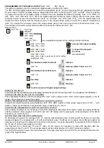
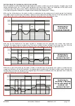
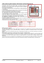
VISUALISING THE INSTANTANEOUS AND AVERAGE PEAK (MAXIMUM) VALUES


By pressing the 

and 

keys simultaneously, the instrument enters into the 

visualisation of the peak (maximum) values: The LED 

will glow. The 

memorised peak (maximum) values, which might be selected by the 

key, 

will be shown on the display 

E

The indication of the value and the value itself will be visualised alternatively 
on the display 

E

If no key is pressed during an interval of time of 10 seconds, the instrument 
will return automatically to the visualisation of measures. 
There are two types of the maximum memorised values: 
The instantaneous maximum memorised value is the maximum reached 
value of the parameter, during 1-second al least. 
The average maximum values (maximum demand) memorise the maximum 


average value of the parameter, reached during the average time. 
The integration for calculating the average values is synchronised every 
time that the instrument is switched on. 
During the visualisation of the maximum memorised values, the values are visualised by alternating the indication of the 
visualised parameter with the measured values. 
The maximum values of the parameters, which are selectable with the 

key, are as follows: 


Parameter


Display

Signalling LED


VL-N maximum instantaneous


PEA   HI


VL-N


VL-N minimum instantaneous


Pea LO


VL-N


VL-L maximum instantaneous


PEA   HI


VL-L


I phase maximum instantaneous


PEA   LO


A


I phase average maximum


AVG  HI


A


NOTE regarding the measures


The refresh time of display is lower than 1 second and it corresponds to the processing time of measure according to the used 
measuring methodology, allowing a comfortable reading of values, also in presence of unexpected deviation of the measured 
parameters. 
Should the case be that the instrument is being used in a single-phase line, please bear on mind that the valid values are referred to 
phase L3. 
Other visualised values shouldn’t be considered, since they correspond to three-phase system. 
In case that the indicated measures aren’t reliable or they are absurd, it’s important to check carefully the current and voltage inputs 
connection, so as the phase sequence. Check that current and voltage correspond to the same phase (on input L1 it will be connected 
phase voltage L1 and the CT will be placed on phase L1), thence terminal S1 of CT will be wired to the relative terminal S1 on the 
instrument. 
If the secondary of the CT is connected to other instruments also, it can be experienced some measuring problems, according with the 
typology of current inputs. Should that be the case, the user should select the option of the instruments type (T) with internal CT’s. 

Summary of Contents for ELM-96

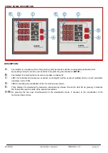
Page 1: ...DELS ELM 96 ACCESSORI ED OPZIONI accessories transparent cover for frontal protection options C1 auxiliary power supply 230 V C2 auxiliary power supply 115 V 1A current inputs for CT 1Amp T current in...

Page 2: ...se to phase power supply 110V 85 145V phase to phase 50 85V phase neutral 230V 300 500V phase to phase 175 290V phase neutral L3 N phase neutral power supply 110V 175 290V phase to phase 100 170V phas...

Page 3: ...ith 3 wires without neutral or with neutral not supplied the N terminal must not be connected ELM 96 instruction manual IM425 U v3 1 pag 3 P1 L1 S1 L2 S1 L3 P1 N S1 S2 P1 P2 LOAD ELM INSERTION ON THRE...

Page 4: ...ERTION ON THREE PHASE LINE WITH 2 CT insertion AARON L1 S1 P1 L2 L3 N S1 S2 P1 P2 LOAD ELM VOLTAGE INSERTION ON THREE PHASE LINE WITH 3 WIRES WITH 2 VT This insertion is possible only with the interna...

Page 5: ...3 wires without neutral or with neutral not supplied the N terminal must not be connected ELM 96 instruction manual IM425 U v3 1 pag 5 L1 L2 L3 S1 S2 P1 P2 LOAD ELM INSERTION ON SINGLE PHASE LINE Only...

Page 6: ...lise on display E C LED s for indicating the measures visualised on display E and the eventual multiplier factor of each parameter reading k kilo x1000 D LED for indicating the visualisation of the me...

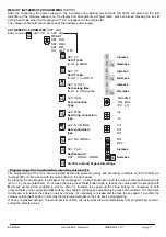
Page 7: ...Decrease Confirm and end of general settings Programming of the transformation rate of the external CT s The programming of the CT s rate considered as the rate between primary and secondary example w...

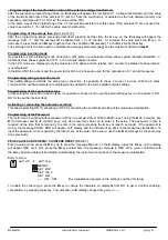
Page 8: ...With the 4 wires connection the neutral parameter are displayed and enabled to use for the digital outputs settings Programming of the synchronism type In this setting for the synchronization type it...

Page 9: ...e ALR Dl Decrease ENTER IN THE SETUP Confirm and end of digital output settings Fromthemeasuresvisualization presstheAkeyforatleast5seconds themessageSeT Up willappearontheEdisplays CHOOSE THE DIGITAL...

Page 10: ...delay Functioning for exceeding the maximum threshold With only the LO threshold set the alarm condition is activated when the parameter set in alarm drop below the threshold The digital output is ena...

Page 11: ...s SELECT THE PARAMETER TO LINK TO THE HOURS COUNTER From the previous setting pressing the B key it s possible to set the hours counter the message SET HR_ appears on the E display Press the A key to...

Page 12: ...urrent LED Hz ON on L3 display is showed the frequency measured on L3 phase on L1 display will appear the message PHASE ROTATION with a bright dash that rotate clockwise to indicate that the phase rot...

Page 13: ...LED L on VL N k VL L k A k VL N VL L In balanced three phase system mode BALANC are available only the visualization 7 and 8 In single phase mode PH L3 the pages displayed are the following ELM 96 ins...

Page 14: ...key are as follows Parameter Display Signalling LED VL N maximum instantaneous PEA HI VL N VL N minimum instantaneous Pea LO VL N VL L maximum instantaneous PEA HI VL L I phase maximum instantaneous P...

Page 15: ...oad 20 impedance at the input 1 M Three phase wiring with 3 or 4 wires and single phase wiring MV connection through external VT with programmable transformation ratio from 1 to 400 Current inputs Fro...

Page 16: ...panel 96 96 90 92 ELM 96 R3 avg 92 20 For other applications please contact with ELCO technical assistance department Via Lago di Molveno 20 36015 Schio VI Tel 39 0445 661722 Fax 39 0445 661792 http...

Reviews: