background image

ELM-961 


instruction manual

IM441-U v0.6 

pag. 4


m

eas

ur

vo

l tage

 in

 pu

ts


m

e


as

ur

e c

u

t i

np

ts


rre 

n

I2  

S1 


I1


I3


L1


L2


L3


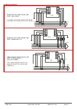
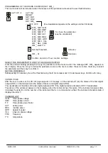
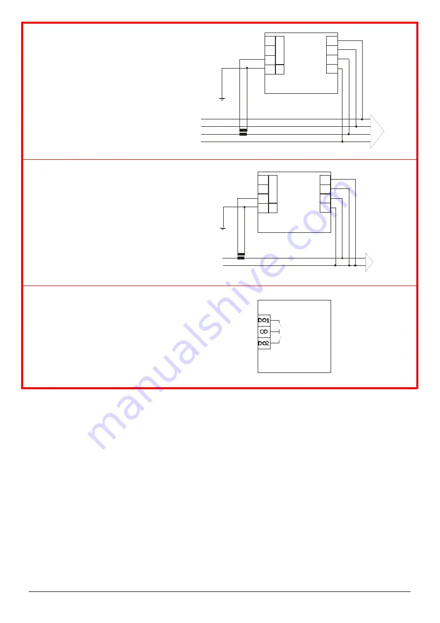
BALANCED  THREE PHASE LINE


C.I. 

S2 


N


ELM


(3EQ mo de)


L1


L2


S1 

S2


L3


P1 

P2


LOAD


me

as

ur

vo

l ta

ge

 in

 put

s


m

eas

ur

e c

ur

re

 nt

 inpu

 ts


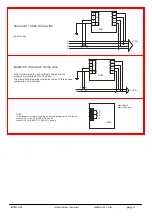
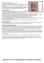
INSERTION ON SINGLE PHASE LINE


I1


I2  

S1 


I3


L1


L2


L3


if the  mu lt im eters  a re  used  on  sing le  pha se  line ,  th e 
m easure  are  ref erred  a t  th e  L 3  ph ase.


The oth ers  dat a  displayed  re la tives  a t  value  o f  th re e  p hase 

syste m  a re  no t  to  consid er.


C. I. 

S2 


N


ELM


S1 

S2


L


P1 

P2


N


LOAD


Max 150mA 
Max 230Vac/dc


D

 igi

 ta

 l 

Ou

 tp

 ut


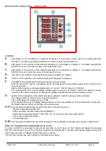
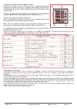
NOTE:


in the instrum ent version w ith  digital  outputs  programmed    lik e  “pulse”


output DO1 for ACTIVE ENER GY puls es 
output DO2 for R EAC TIVE  ENERGY  pulses


ELM


Summary of Contents for ELM-961

Page 1: ...internal CT digital output in alternative to the serial port serial port in alternative to the digital output power supply different from standard version current input 1A MEASURED PARAMETERS paramete...

Page 2: ...400V 300 500V phase to phase 175 290V phase neutral 230V 175 290V phase to phase 130 170V phase neutral L2 L3 phase to phase power supply 110V 85 145V phase to phase 50 85V phase neutral 230V 300 500V...

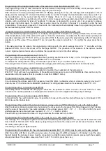
Page 3: ...IRES ELM on line with 3 wires without neutral or with neutral not supplied the N terminal must not be connected L1 S1 P1 S1 L2 P1 L3 N S1 S2 P1 P2 LOAD I1 I3 VL1 VL2 VL3 INSERTION ON THREE PHASE LINE...

Page 4: ...N ON SINGLE PHASE LINE I1 I2 S1 I3 VL1 VL2 VL3 if the multimeters are used on single phase line the measure are referred at the L3 phase The others data displayed relatives at value of three phase sys...

Page 5: ...the values of the active reactive and apparent energy counters If it s selected with the A and B keys the display indicates the maximum and average values G display for the visualization of the electr...

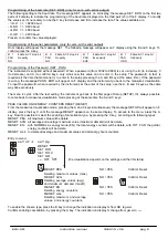
Page 6: ...kVAr pulse version with digital output 01 0 kW kVAr pulse 0 10 kW kVAr pulse 0 01 kW kVAr pulse seT TPL Increase from 100 to 500 mS in step by 100 mS Decrease version with digital output seT ID ADR In...

Page 7: ...decrease it press the C key To confirm it press the A key The average time is the time used to calculate the average parameters avg and the maximum demand maxD Programming of the energy visualization...

Page 8: ...rd when required by the instrument at the enter of the setup use the A B and C keys as the same way done previously The menu is cyclic After the last setting the instrument go back to the first page o...

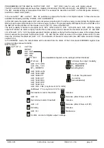
Page 9: ...ALR LO With ALR SYS 123 the digital output will function as alarm verifying that the maximum value of the single phases doesn t exceed the maximum threshold set ALR HI and that the minimum value of t...

Page 10: ...the set SET THE HIGH AND THE LOW THRESHOLDS On F display will appear the message ALR Hi with the high threshold value confirming with the A key on the same display will appear the message ALR LO with...

Page 11: ...ime the B key to select the parameter and the A key to confirm it SET THE THRESHOLD Subsequently it s necessary to set the threshold using the B to increase and C to decrease keys Confirm with A key I...

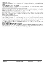
Page 12: ...all the measures appear on the L3 display Visualization section 2 At the same way of the section 1 press the C button to select the parameter that can be displayed and indicated from E LED The voltag...

Page 13: ...s max maxD avg I L1 max avg I L2 max avg I L3 max avg phase currents maximum of average phase currents max demand max maxD avg W max avg VAr max avg VA max avg three phase power maximum of average thr...

Page 14: ...se speed Not shielded connection As shown in the diagram it is necessary to place a serial RS232 485 converter between the RS232 PC s outlet and the instrument s it s necessary to insert a line termin...

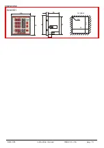
Page 15: ...ELM 961 instruction manual IM441 U v0 6 pag 15 DIMENSIONS ELM 961 96 9 56 cut panel 96 96 R3 92 90 92 20...

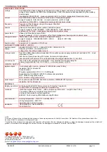
Page 16: ...1 to 400 0 current inputs from 0 02 to 5A permanent overload 30 from external TA with secondary 5A primary programmable from 5 to 10000A auto consumption 0 5VA INPUTS OUTPUTS digital outputs Two outpu...

Reviews: