16
Installation
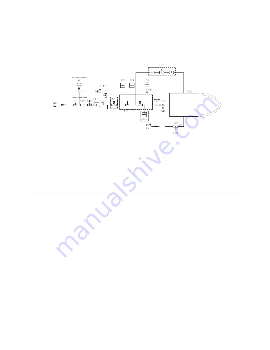
Gas train description
Gas valves and instruments
group
The gas trains must be dimensioned to
suit the throughput required and the
available gas pressure. The gas valves
and instruments group is defined on a
system-specific basis.
The following must be taken into consi-
deration:
• Burner output,
• Combustion chamber counterpres
sure,
• Gas pressure loss in the burner head,
• Gas pressure losses in the gas fit
tings and instruments.
The total drop in gas pressure must
always be lower than the available gas
flow pressure.
100
Burner
101
Impulse pipe gas pressure
120
Air flap
141
Ball valve
142
Gas filter
144
Gas pressure regulator
145
Safety shut-off valve (SSV)
148
Safety relief valve (SRV)
150
Gas control butterfly
151
Gas double valve with integrated gas pressure
regulator (Siemens system illustrated)
155
Ignition unit
313
Min. gas pressure switch
314
Gas pressure switch for valve leak check or valve
leak checker
349
Actuator
Options in accordance with country-specific requirements:
143
Pressure gauge with pushbutton valve
147
Test burner with pushbutton valve
148
Compensator
154
Gas safety valve (additional)
313a Max. gas pressure switch
Gas train to EN 676, high pressure
12/2011 14 072 205
Summary of Contents for Low-NOx N10.12000.30 G-EU2
Page 33: ...34 Manufacturer s declaration...


