background image

05/2005 - Art. Nr. 13 018 071A

16

Inbetriebnahme

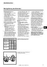
Einstellung Druckwächter

Einstellung Gasdruckwächter

·

Zur Einstellung Abschaltdruckes : Deckel
des Gasdruckwächters abnehmen.

·

Brenner starten und Gasdruck vor
Armatur durch androsseln des Kugel-
hahns auf gewünschten Abschaltwert
einstellen.

·

Einstellscheibe im Uhrzeigersinn
drehen, bis Gasdruckwächter
Brenner abschaltet.

Einstellung Luftdruckwächter

·

Brenner auf Kleinlast einstellen.

·

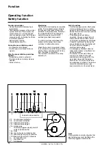
Skalenwert solange erhöhen bis Luft-
druckwächter Brenner abschaltet.

·

Luftdruckwächter auf 70% des
Abschaltwertes einstellen.

Funktionskontrolle

Eine Sicherheitstechnische Überprü-
fung der Flammenüberwachung muß
sowohl bei der erstmaligen Inbetrieb-
nahme wie auch nach Revisionen oder
längerem Stillstand der Anlage vorge-
nommen werden.

Anlaufversuch mit geschlossenem
Gasventil : nach Ende der Sicher-
heitszeit muß der Feuerungsautomat
auf Störung gehen !

Normaler Anlauf ; wenn Brenner in
Betrieb, Gasventil schließen : nach
Flammenausfall muß der Feuerungs-
automat auf Störung gehen !

Normaler Anlauf ; während Vorbelüf-
tung oder Betrieb Luftwächterkontakt
unterbrechen : Feuerungsautomat
muß sofort auf Störung gehen !

Vor Anlauf Luftdruckwächter überbrü-
cken : Brenner schaltet für ca. 2-3
sec. ein, anschließend erfolgt Störab-
schaltung. Nach 10 sec. wird diese
Kurzstörung vom Automaten selbst-
tätig zurückgesetzt und ein zweiter
Anlaufversuch erfolgt (Motor schaltet
für 2-3 sec. ein). Ist der LW-Kontakt
immer noch geschlossen (z.B. ver-
schweißt) erfolgt eine echte Störab-
schaltung. Hat der LW-Kontakt
jedoch innerhalb dieser 10 sec.

geöffnet (z.B. durch auslaufenden
Motor), erfolgt ein normaler Betriebs-
anlauf.

Summary of Contents for VECTRON G 03.240 DUO PLUS

Page 1: ...pare parts list Pi ces de rechange Wisselstukkenlijst 37 44 Elektro und Hydraulikschema Electric and hydraulic diagrams Sch mas lectrique et hydraulique Elektrische en hydraulische schema 45 48 Operat...

Page 2: ...Es d rfen nur Dichtungsmaterialien verwendet werden die DVGW gepr ft und zugelassen sind Dichtheit der Ver bindungsstellen mit schaumbildenden Mitteln oder hnlichen die keine Korrosion verursachen pr...

Page 3: ...utomat SG 513 Flammenw chter Ionisationssonde Z ndtransformator EBI 1 x 11 kV Luftdruckw chter LGW3 A2 Schalldruckpegel nach VDI2715 dB A 69 72 Max Umgebungstemperatur 60 C Das Regelverh ltnis ist ein...

Page 4: ...rga bestation notwendigen Gasflie drucks ist zus tzlich der Widerstand der Bren nerzuleitung einschlie lich Armaturen Kugelhahn TAS zus tzliche Filter oder Z hler zu ber cksichtigen G 03 240 DUO PLUS...

Page 5: ...se 7 Typenschild 8 Brennerrohr 9 Zugsicherung Elektroanschlu 10 Elektroanschlu 7 polig 10 1 Elektroanschlu 4 polig Temperatur regler 16 Gasarmaturanschlu flansch 18 Abdeckhaube 19 Entriegelungsknopf 1...

Page 6: ...me nippel M4 nach Ventil 2 12 Einstellschraube Nullstellung N 13 Anschlu Feuerraumdruckleitung pF R1 8 14 Anschlu Gasdruckleitung pG R1 8 15 Ausgangsflansch 16 Druckme nippel pa nach Ventil1 beidseiti...

Page 7: ...tionsstrom mu min 8 A betragen Sicherheitsfunktionen Bildet sich beim Start des Brenners Gasfreigabe keine Flamme so wird nach Ablauf der Sicherheitszeit von max 3 Sekunden der Brenner abge schaltet d...

Page 8: ...ndtrafo Flammenw chter Stellmotor SM St rung Entriegelung Der Gasfeuerungsautomat SG 513 steuert und berwacht den Gebl sebrenner Durch den mikroprozessor gesteuerten Programmablauf ergeben sich u erst...

Page 9: ...6 5 23 4 25 26 Fernentriegelung St rungsleuchte Betriebsstundenz hler Stromversorgung 230V Am Steckersockel unterhalb des Feue rungsautomaten sind diverse Steck pl tze f r den Anschlu externer Ger te...

Page 10: ...SM Steckers und Phase der Ventil 2 7 Klemme T2 am Wiel Stecker 7P 35 Klemme B4 am Wiel Secker 7P 5 des SM Steckers und Phase der Ventil 1 Klemme 5 des Automaten 9 Klemme 9 des Automaten durch Br cke o...

Page 11: ...Ausmauerung 5 wie im nebenste henden Bild erforderlich Die Ausmaue rung darf die Flammrohrvorderkante nicht berragen und mit maximal 60 konisch zulaufen Der Luftspalt zwischen Ausmauerung und Brennerr...

Page 12: ...Handabsperrventil vor der Gas Kom pakteinheit schlie en Steht kein ausreichender Gasdruck vor der Gaskompaktarmatur an ggf Gasdruckw chter br cken Klemme 2 und 3 hierzu Brenner spannungs frei machen...

Page 13: ...tellung auf Fl ssiggasbetrieb St tzgasblende 3 und Stauscheibe 4 demontieren Zwischenst ck 5 mit Geh use geliefert montieren Stauscheibe 4 und St tzgasblende 3 wieder montieren Montage Mischeinrichtun...

Page 14: ...Position der Luftklappe wird durch Einstellung der Nocken I IV festgelegt Funktion der Nocken Nocke Funktion I Vollast II Abschlu bei Stillstand III Z ndlast IV Kleinlast zwei fest miteinander verbun...

Page 15: ...ieren Die gew nschte Teillast festlegen Falls erforderlich Brennerleistung Kleinlast ber Einstellung Nocke IV des Stellantriebes justieren Luftmenge reduzieren Nocke IV kleineren Skalenwert einstellen...

Page 16: ...er l ngerem Stillstand der Anlage vorge nommen werden Anlaufversuch mit geschlossenem Gasventil nach Ende der Sicher heitszeit mu der Feuerungsautomat auf St rung gehen Normaler Anlauf wenn Brenner in...

Page 17: ...die Feuerraumt r zu ffnen oder den Brenner auszubauen 1 Zugang ber die Feuerraumt r Die drei Schrauben V auf TF l sen Das Flammrohr nach vorne heraus ziehen Flammrohr wieder montieren Zwischenraum zwi...

Page 18: ...ckw chter berpr fen oder Gaskom pakteinheit austauschen Luftdruckw chter einstellen austauschen Thermostate einstellen oder austauschen Brenner startet bei Einschaltung ganz kurz schaltet ab und gibt...

Page 19: ...All seals and sealing material used must be DVGW tested and approved Check seals and connection points for possible leaks with a suitable non corrosive foam product Bleed the gas conduit before using...

Page 20: ...Ignition transformer EBI 1 x 11 kV Air pressure switch LGW3 A2 Sound level conforms to VDI2715 dB A 69 72 Max ambient temperature 60 C The control ratio is a medium value and may change according to...

Page 21: ...0 42 13 12 260 33 12 49 15 15 280 39 14 57 18 17 300 44 16 65 20 20 Selection of gas valve assembly The gas pressure loss indicated in the table is to be added to the furnace pressure reading in mbar...

Page 22: ...F6 Air pressure switch M1 Electric motor T1 Ignition transformer Y10 Servomotor for air control 5 Housing 7 Identification plate 8 Burner tube 9 Fuse for electrical connection 10 Electrical connection...

Page 23: ...etting screw for zero value N 13 Connection for furnace pressure take off pipe pF R1 8 14 Connection for gas pressure take off pipe pG R1 8 15 Output flange 16 Pressure measuring nipple pa after valve...

Page 24: ...e ionisation current must not drop below 8 A Safety functions If no flame appears when the burner starts up release of gas a safety period of up to three seconds elapses before the burner shuts down a...

Page 25: ...ntrolled program sequence ensures the maximum consistency of the time periods involved regardless of fluctuations in the power supply voltage or ambient temperature The design of the automatic unit pr...

Page 26: ...ollows Use a small screwdriver to snap off the plastic cover over the corresponding plug socket Insert the cable towards the retainer outlet see illustrations 20 21 10 1 8 4 24 2 11 22 6 5 23 4 25 26...

Page 27: ...phase of valve 2 7 Terminal T2 at Wiel plug 7P 35 Terminal B4 at Wiel plug 7P 5 of SM plug and phase of valve 1 terminal 5 of control unit 9 Terminal 9 of control unit via bridge or temperature contro...

Page 28: ...e brickwork must not protrude beyond the leading edge of the flame tube and should have a maximum conical angle of 60 The space between the brickwork and burner should be filled with an elastic non in...

Page 29: ...f gas pressure upstream of valve assembly is insufficient bypass the gas pressure switch terminal 2 and 3 if necessary shutting down the power supply to the burner Activate the boiler to start up the...

Page 30: ...r specifications given Conversion to propane gas operation Remove gas diffusor 3 and turbulator 4 Fit distance piece 5 supplied with burner body Refit turbulator 4 and gas diffusor 3 Fitting burner he...

Page 31: ...Suction side airflow regulation is carried out using an air flap This is actuated by servomotor Y10 The position of the air flap is determined by adjusting cams I IV Airflow control in the burner hea...

Page 32: ...required adjust the burner output capacity low load via cam IV of the actuator To reduce the air quantity set cam IV to lower scale value servomotor adapts position automatically To increase the air q...

Page 33: ...wn period Startup attempt with closed gas valve Note that the control unit MUST go into malfunction mode at the end of the safety period Normal startup if burner is in operation shut gas valve after t...

Page 34: ...t of the flame tube To carry out this procedure the furnace door must be opened or the burner removed 1 Access via furnace door Loosen the three screws V on TF Remove the flame tube by pulling it towa...

Page 35: ...place compact gas fired unit Readjust or replace air pressure switch Readjust or replace thermostat Burner activates briefly at startup then shuts down and emits following signal x x y y y y y y y y C...

Page 36: ...05 2005 Art Nr 13 018 071A 36...

Page 37: ...071A 37 Pi ces de rechange Ersatzteilliste Wisselstukkenlijst Spare parts list VECTRON G 03 240 DUO PLUS VECTRON G 03 300 DUO PLUS G 03 240 DUO PLUS KN KL 13 011 825 13 011 826 G 03 300 DUO PLUS KN KL...

Page 38: ...05 2005 Art Nr 13 018 071A 38...

Page 39: ...ans relais C ble vanne gaz avec relais seulement pour la Belgique Kabel Gasventil ohne Trennrelais Kabel Gasventil mit Trennrelais nur f r Belgien Kabel gasventiel zonder relais Kabel gasventiel nuur...

Page 40: ...ise C 2P c ble transfo Kabel m Stecker Z ndtrafo Stekker cable transformator Plug cable ignition transfo 13 012 226 13 012 226 61 2 Coude R1 8 Messnippel Winkel R1 8 Meetnippel kniestuk 1 8 Pressure t...

Page 41: ...41 05 2005 Art Nr 13 018 071A...

Page 42: ...05 2005 Art Nr 13 018 071A 42...

Page 43: ...9 722 146 810 4843 467 2 Bride Flansch Flens Flange 407 Rp 3 4 13 010 074 3333 262 670 412 Rp 1 1 4 13 010 085 147 843 7414 468 Ensemble tubes pression Druckabnahmerohr m Verschr Set drukbuis Pressure...

Page 44: ...enance parts ELCO s performance warranty for them over time under commercial conditions does not apply Les pi ces d entretien sont des pi ces qui devraient tre remplac es titre pr ventif au cours de l...

Page 45: ...schema Electric and hydraulic diagrams Sch mas lectrique et hydraulique Elektrische en hydraulische schema VECTRON G 03 240 DUO PLUS VECTRON G 03 300 DUO PLUS G 03 240 DUO PLUS KN KL 13 011 825 13 011...

Page 46: ...h l B e l f t u n g V e n t i l p e r m C o n t i n u o u s v e n t i l V o o r t d u r e n d e v e n t i l 1 1 O P T I O N F l a m m e n w c h t e r U V D C e l l u l e U V D C e l l U V D F o t o c...

Page 47: ...i t c o m p a c t e G a s v a l v e u n i t T h p r s c u r i t N u r f r B E P o u r B E u n i q u e m e n t O n l y f o r B E S o l o p e r B E A l l e e n v o o r B E S o l o p a r a B E 2 1 2 1 B...

Page 48: ...o t o r w c h t e r m i n G a s d r u c k T 1 Y 1 0 Z n d t r a f o S t e l l a n t r i e b S 1 M a n o s t a t d a i r M a n o s t a t g a z m i n S e r v o m o t e u r V o y a n t d f a u t b r u l...

Page 49: ......

Page 50: ...05 2005 Art Nr 13 018 071A 50...

Page 51: ...51 05 2005 Art Nr 13 018 071A...

Page 52: ...Sarganserstrasse 100 7324 Vilters 0848 808 808 ELCO GmbH Dreieichstr 10 64546 M rfelden Walldorf 0180 3526180 ELCO France 18 rue des Buchillons 74106 Annemasse 0450877624 ELCO Rendamax B V Amsterdamse...

Reviews: