background image

24

09/2005 - Art. Nr. 13 019 526A

Start-up

Adjustment mode
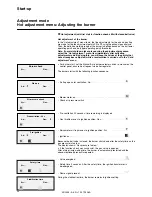
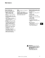
Hot adjustment menu: Adjusting the burner

Ž

Hot adjustment (with first start for function check, still with closed ball valve)

Hot adjustment of the burner

In the “Hot adjustment” menu items, the fine adjustments for the air and gas flap
are made for the ten adjustment points P0 to P9 using the exhaust gas analysis.
Then, the definitive working range of the burner is defined based on the bu (lower
operating point) and bo (upper operating point) thresholds.

Note: if normal shutdown takes place during the adjustment procedure,
select the “Hot adjustment” menu item immediately after activating
adjustment mode. By doing this, you will keep the values of the points that
have already been adjusted, while a recalculation is carried out in the “Cold
adjustment” menu.

·

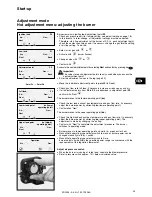
For burner start, set the Manual/Auto burner selector switch to manual on the
control panel, ensure heat request via boiler regulator.

The burner starts with the following function sequence:

Air flap opens for ventilation. Air: . . . . . . . . . . . . . . . . . . . . . . . . .

Blower motor on. . . . . . . . . . . . . . . . . . . . . . . . . . . . . . . . . . . . .

Check air pressure switch

Pre-ventilation 20 seconds: time remaining is displayed.

Gas throttle moves to ignition position. Gas: . . . . . . . . . . . . . . . . .

Servomotor air flap moves to ignition position. Air: . . . . . . . . . . . .

Ignition on. . . . . . . . . . . . . . . . . . . . . . . . . . . . . . . . . . . . . . . . .

Because the ball valve is closed, the burner shuts down after the safety time as the
gas pressure is too low.
The display shows: “Gas pressure too low”.

·

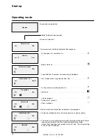
If the function check was successful, the gas valve is opened.

After a two-minute waiting time, the burner is automatically restarted and the
above-mentioned process is repeated.

Valve energised. . . . . . . . . . . . . . . . . . . . . . . . . . . . . . . . . . . . .

Safety time 3 seconds. After the safety time, the ignition transformer is
de-energised.

Flame signal present. . . . . . . . . . . . . . . . . . . . . . . . . . . . . . . . . .

During the stabilisation time, the burner remains in ignition setting.

Burner check

Air: -

Gas: -

Start-up

Air pressure check

Pre-ventilation: 20 s

Air: -

Gas:

Pre-ignition

Air:

Gas: -

Safety time

Stabilisation time

Air:

Gas: -

Air: -

Gas: -

Air: -

Gas: -

Air: -

Gas: -

Summary of Contents for VECTRON G 05.1000 MODULO

Page 1: ...ners 2 31 VECTRON G 05 700 MODULO VECTRON G 05 1000 MODULO Ersatzteilliste Spare parts list Pi ces de rechange Wisselstukkenlijst Elektro und Hydraulikschema Electric and hydraulic diagrams Sch mas le...

Page 2: ...essure regulator 19 Checks before start up 20 Control unit auto test 20 Adjustment mode 21 25 Access 21 Parameters menu 21 22 Cold adjustment menu 23 Hot adjustment menu 24 25 Operating mode 26 Info m...

Page 3: ...nd energy saving operation DIN 4705 Calculation of flue dimensions EN 676 Forced draught gas burners EN 226 Connection to heating systems of vaporising fuel oil and forced draught gas burners VDE 0116...

Page 4: ...ustion chamber board Burner head with flange seal and fixing screws Gas valve assembly with gas throttle module DMV gas valve with built in pocket filter or with external filter connection parts screw...

Page 5: ...flow pressure m bar 20 100 Burner motor 2800 min 230 400 V 50 Hz 1 1 kW 230 400 V 50 Hz 1 5 kW Combustion control unit flame sensor MPA 22 ionisation alternative IRD probe Power consumption W 1800 200...

Page 6: ...l gas E Gas flow pressure 20 mbar N B at gas valve inlet Required burner power 700 kW Combustion chamber pressure with boiler rated load 2 5 mbar Condition working point must be within the burner s pe...

Page 7: ...of no less than 0 60 m on each side of the burner for maintenance purposes Gas valve assembly The valve assembly can be fitted on the left or the right Overview Dimensional drawings and measurements G...

Page 8: ...erating overpressure 500 mbar Inlet pressure range pe 15 500 mbar Voltage frequency 230 V 50 60 Hz The gas valve assembly consists of a gas throttle controlled by a servomotor a DMV SE gas valve a gas...

Page 9: ...9 09 2005 Art Nr 13 019 526A Overview Hydraulics diagram EN...

Page 10: ...l reduction of burner power All control elements are visible externally A removable transparent cover clipped to the burner cover gives access to the monitoring and control elements for setting and op...

Page 11: ...ustment point P0 a separate ignition load can be defined for the burner The thresholds for the normal range are defined with adjustment points bu and bo lower operasssting point and upper operating po...

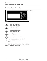
Page 12: ...the cursor clockwise Reducing the marked value Unlocking the combustion control unit Red light diode flashes in the event of a fault Overview Combustion control unit MPA 22 Display and operating unit...

Page 13: ...nts Setting for points P0 to P9 Temperature controller on Operating mode Ready for operation Temperature controller on Operation t 5 s t 5 s Start up Check air pressure switch Pre ventilation Safety t...

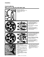
Page 14: ...upper bolts into the two slots in the burner head flange Press the burner housing against the burner head flange and tighten the 4 nuts The housing can be mounted above the axis of the burner head if...

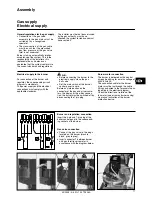
Page 15: ...re external filter 1 Note the direction of the flow Fit a thermally triggered safety valve and a gas ball valve provided by manufacturer before the gas valve m If the position of the gas train is angl...

Page 16: ...abelled A 5 outwards facing slots and 1 inwards facing slot should be left covered by sleeve E Secure the turbulator with 6 drilled M5x6 screws F On the gas diffusers labelled B 5 outwards facing slot...

Page 17: ...rection of rotation of the fan motor see arrow on burner casing via manual activation of the burner protection device Gas valve connection Connect the gas valve to the plugs located on the burner blac...

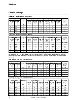
Page 18: ...ropane gas settings table G 05 700 MODULO Propane gas settings table G 05 1000 MODULO Burner power Dimension Y mm Air flap opening Gas throttle opening Pressure regulator setting pVA mbar Low load kW...

Page 19: ...thin this time the gas pressure switch must release If there is insufficient gas pressure the burner starting is interrupted and a waiting time of 2 minutes starts Start up is then attempted again The...

Page 20: ...eat generator and regulation producer Check that the gas type and gas pressure are appropriate to the burner Check the gas conduit for leaks Vent the fuel supply pipes Check the flame pipe insertion d...

Page 21: ...t range 0 minutes no waiting time to 100 minutes The pulse factor gives the number of pulses that the control unit receives from the gas counter with the flow rate of a cubic metre of natural gas acce...

Page 22: ...e error log Leak check Y Yes N No With this function you can deactivate the valve leak check Valve 1 check time For proper execution of the leak check at least the 6 seconds set in the factory are req...

Page 23: ...tment with or Confirm with Adjust air and gas setting Position the cursor on air or gas with or Activate with cursor flashes Set new value with or Confirm with Switch between adjustment points P9 P1 P...

Page 24: ...r switch to manual on the control panel ensure heat request via boiler regulator The burner starts with the following function sequence Air flap opens for ventilation Air Blower motor on Check air pre...

Page 25: ...oint 9 full load Check gas flow rate full load if necessary increase or reduce gas and air If all adjustment points from P0 to P9 are optimised in adjustment point P9 confirm with Next The burner move...

Page 26: ...s time remaining is displayed Gas throttle moves to ignition position Gas Air flap moves to ignition position Air Ignition on Valve energised Safety time 3 seconds Flame formation After the safety tim...

Page 27: ...gain Error 0 Error 1 Error 2 Error 3 Error 4 Error 5 Fuel Gas Value P0 Value P1 Value P2 Value P3 Value P4 Value P5 Value P6 Value P7 Value P8 Value P9 Voice mode can be activated with the button duri...

Page 28: ...he ignition electrodes and the mixing unit Disconnect the 2 ignition cables from the ignition transformer Remove the grommet for the two cables from the cover by pressing into the burner head Unscrew...

Page 29: ...Remove the mixer control ignition device Loosen the electrical connections Remove the gas valve assembly Unscrew the gas connection 2 M8 nuts Loosen the burner housing 2 M8 screws and remove Do not da...

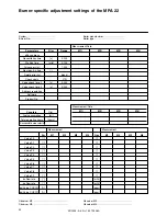
Page 30: ...Valve check time 2 s 0 240 Address regulation Software Product No Counters Dim Fuel consumption m Total operating hours hours Successful burner starts Measurement Date M1 M2 M3 M4 Measurement Measure...

Page 31: ...Motor defective Control unit servomotors feedback not correct Establish connection Check replace Check replace Control unit servomotors Check replace Motor only runs briefly Air pressure switch does...

Page 32: ...00 7324 Vilters 0848 808 808 ELCO GmbH Dreieichstr 10 64546 M rfelden Walldorf 0180 3526180 ELCO France 18 rue des Buchillons 74106 Annemasse 0450877624 ELCO Rendamax B V Amsterdamsestraatweg 27 1410...

Reviews: