05/2005 - Art. Nr. 13 018 106A
44
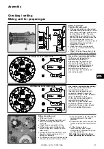
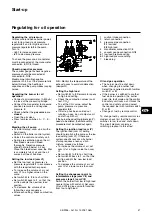
A
Scale (0° to 90°) indicating the servo
drive setting
B
Coupling between air flap and
servomotor
C
Air flap setting indicator
Checking the air flap setting
The air flap setting can be read from
the servomotor scale
A
.
If the burner is mounted above the
head, the air flap setting can be read
from scale on the disk
2
.
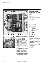
Function of the cams
Cam
Function
I
High load setting (oil and gas)
II
Closure on shutdown
III
Ignition load (gas)
IV
Ignition load (oil)
V
Low load (gas)
VI
Low load (oil)
VII
Opening of magnetic oil valve Y2
(intermediate stage)
VIII
Changeover from pressure
stage 1 to pressure stage 2
through closure magnetic valve
Y5.
Setting
·
Set the cams manually or with the
key provided, in accordance with the
required burner power and the
values indicated in the setting table.
The following relationships must be
observed between cam settings:
·
When operating with gas, the
ignition load (cam III) setting can be
above or below the low load (cam V)
setting.
·
When operating with oil, ignition load
(cam IV) and low load (cam VI)
should have the same settings.
·
When operating with oil, changeover
to the intermediate load (cam VII)
should be set below changeover to
pressure stage 2 (cam VIII) and
above the low load (oil) (cam VI)
setting.
·
The setting for changeover to
pressure stage 2 (cam VIII) must be
below the high load (cam I) setting.
Start-up
Regulating the air supply
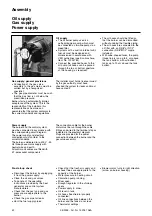
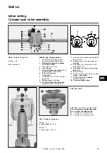
1
Cam setting indicator
2
Eight adjustable cams
3
Disk with scale;
indicates the air flap setting;
4
Connection strip
5
Cam setting key
6
Servomotor identification
C
Button to disengage the cam
cylinder (with locking pin)
Servomotor
The air flap is adjusted via an electrical
servomotor (type SQM50 / 481 A2).
The eight cams of the servomotor are
used to adjust the air flap setting to the
various points of the burner’s operation.
When operating with gas, a three-point
regulator is available to give step-free
regulation of the volume of combustion
air.


