05/2005 - Art. Nr. 13 018 106A
48
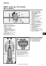
Checking the ignition electrodes
and the mixing unit.
·
Disconnect the 2 ignition cables
from the ignition transformer.
·
Withdraw the flame monitor.
·
Remove the grommet for the two
cables from the cover by pressing
into the burner head.
·
Remove the oil pressure pipes.
·
Unscrew completely the 3 screws
securing the cover.
·
Slip the cover off over the cables.
·
Loosen the side screw securing the
mixing unit.
·
Withdraw the mixing and ignition
unit.
·
Check the condition of the turbulator.
·
If necessary, replace nozzles.
·
Check the position of the ignition
electrodes and the turbulator.
·
If necessary, remove dust from the
parts accessible with the cover
removed.
·
Check the presence and condition of
the O-ring seal when assembling.
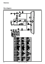
Cleaning the fan
·
Disconnect the motor by unplugging
it from the power supply.
·
Unscrew the 7 screws of the motor
panel.
·
Remove the panel and motor, taking
care not to damage the pressure
take-off pipe of the differential air
pressure switch.
·
“Dry” clean the air pressure pipes.
·
Do not use pressurized materials.
·
Take out the 4 screws securing the
air guiding piece.
·
Thoroughly clean the air duct and
fan.
·
Re-assemble.
Burner and boiler servicing can
only carried out by a trained
specialist. The system operator is
advised to take out a service
contract to guarantee regular
servicing.
Checking the exhaust gas
temperature
·
Check the exhaust gas temperature.
·
Clean the boiler if the exhaust gas
temperature is over 30 K above the
start-up value.
Maintenance
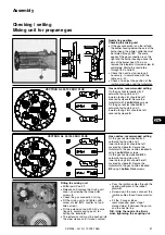
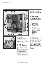
A1
control and safety unit
B10
measure point [µA DC]
F6
air pressure switch
F12
motor protection relay
K1
motor protection
K5-K6-K7 time delay switches
M1
blower motor
SA1
On the control unit, display of:
- the programm,
- the faults: red control lamp
lights up, and push button to
release the fault.
TC
control panel
TC
T1
ignition transformer
Y10
servomotor
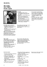
9
blast tube
15
cover
102
motor/pump
113
air box


