09/2018 - Art. Nr. 4200 1092 1400A
18
Overview
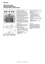
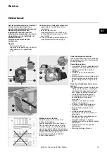
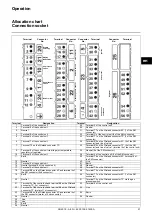
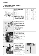
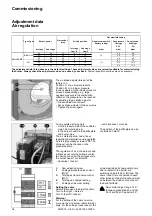
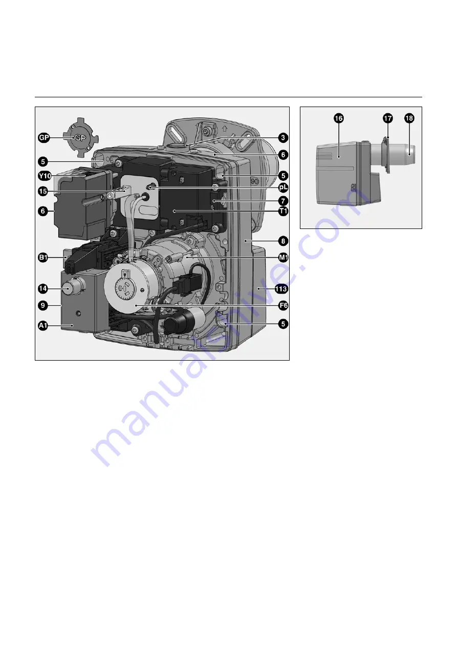
Burner description
A1
Control and safety unit
B1
Ionisation bridge
F6
Air pressure switch
GP
Sealing washer for Liquefied
Petroleum Gas
M1
Electric motor
pL
Air pressure nipple
T1
Ignition transformer
Y10
Servomotor for air control
3
Gas train connecting flange
5
Fastening screws for equipment plate
7
Securing device (service)
8
Housing
9
Electrical connection (covered)
14
Release knob
15
Gas head adjusting screw
16
Cover
17
Burner connecting flange
18
Burner tube
113
Air intake box


