09/2018 - Art. Nr. 4200 1092 1400A
22
Operation
Operating mode
Safety function
Description of the function
- Control thermostat requests heat.
- The control program of the control unit
starts if the air pressure switch contact
is in the rest position and the gas
pressure switch signals sufficient gas
pressure.
- Burner motor operational
- Pre-ventilation period of 24 s
During the pre-ventilation time
- the air pressure is monitored
- the combustion chamber is monitored
to detect any flame signals.
At the end of the pre-ventilation time
- the ignition is switched on
- the main and safety solenoid valves
are opened.
- burner start-up
Monitoring
The flame is monitored by an ionisation
probe. The probe is fitted with insulation
to the gas head and is routed through
the turbulator into the flame zone. The
probe must not have any electrical
contact with earthed parts. The burner
switches to malfunction if a short circuit
occurs between the probe and the
burner earth. During burner operation,
an ionised zone is produced in the gas
flame through which a rectified current
flows from the probe to the burner tip.
The 2
nd
stage ionisation current must be
at least 7 µA.
Safety functions
- If no flame is produced when the
burner is started (gas release), the
burner will be switched off at the end
of the safety time lasting no more than
3 seconds and the gas valve closes.
- In the event of flame failure during
operation, the gas supply is cut off
within a second and the automatic
combustion control unit triggers a
safety shutdown.
- The burner does not operate if there is
a lack of air during the pre-ventilation
period. A safety shutdown is triggered.
- A safety shutdown also occurs if there
is a lack of air during operation.
- The burner does not operate if there is
a lack of gas. If there is a lack of gas
during operation, the gas valve closes
and the burner switches off. There is
no safety shutdown. The burner starts
automatically if the gas pressure is
restored.
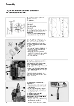
CH note
In accordance with SSIGE instructions,
it is compulsory to install a gas safety
valve (mark
1
) in the pipe
DE Note
In compliance with the reference layout
applicable to boiler rooms, sites with gas
furnaces must be fitted with a thermal
gas shut-off valve (mark
1
).
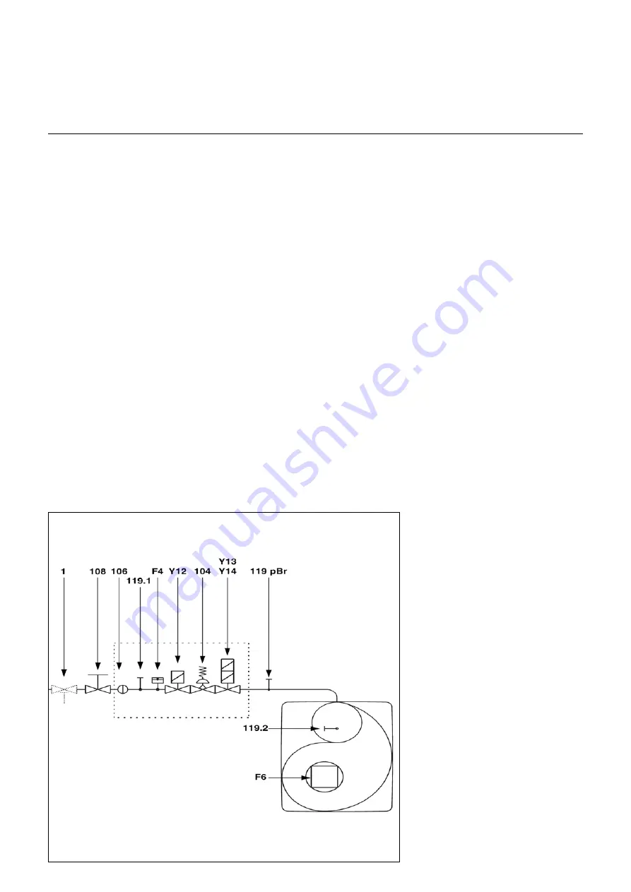
F4
Gas pressure switch
F6
Air pressure switch
Y12 Safety solenoid valve
Y13 Solenoid valve, 1st stage
Y14 Solenoid valve, 2nd stage
1
Thermal shut-off valve (to be
installed by the installer)
104 Gas pressure regulator
106 Screen
108 Gas cut-out valve (to be installed
by the installer)
119pBrGas pressure measuring point at
the valve outlet
119.1Gas pressure measuring point
upstream of the valves
119.2Air pressure measuring point
Compact train

