09/2018 - Art. Nr. 4200 1092 1400A
24
Assembly
Liquefied Petroleum Gas operation
Electrical connection
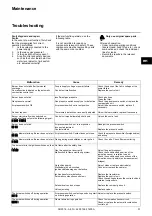
Burner boiler electrical connection
The electrical installation and
connection work must only be carried
out by an authorised specialist.
All applicable rules and regulations must
be observed.
• Check to ensure that the power supply
voltage is as specified (230 V, 50 Hz)
• Burner fuse: 10 A.
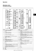
The burner and heat generator are
connected by a 7-pin connector
1
and a
4-pin connector
2
.
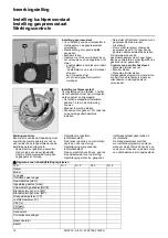
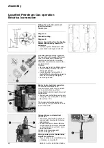
Setting the ionisation probe and
ignition electrode
See diagram
Diagram 1:
Standard setting
Diagram 2:
Burner head setting for older heating
boilers with tendency toward CO
emissions
• Fit the two plates
C
between baffle
plate
A
and natural gas shutter
D
.
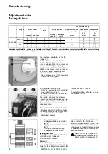
Liquefied Petroleum Gas operation
For operation with Liquefied Petroleum
Gas, it is necessary to replace the
natural gas shutter with a Liquefied
Petroleum Gas shutter secured to the
equipment plate.
To do so:
• Remove gas head (see Maintenance).
• Loosen baffle plate
D
and remove
natural gas shutter.
• Install Liquefied Petroleum Gas
shutter
GP
with stamp facing upwards
and screw on baffle plate tightly.
• Refit the gas head.
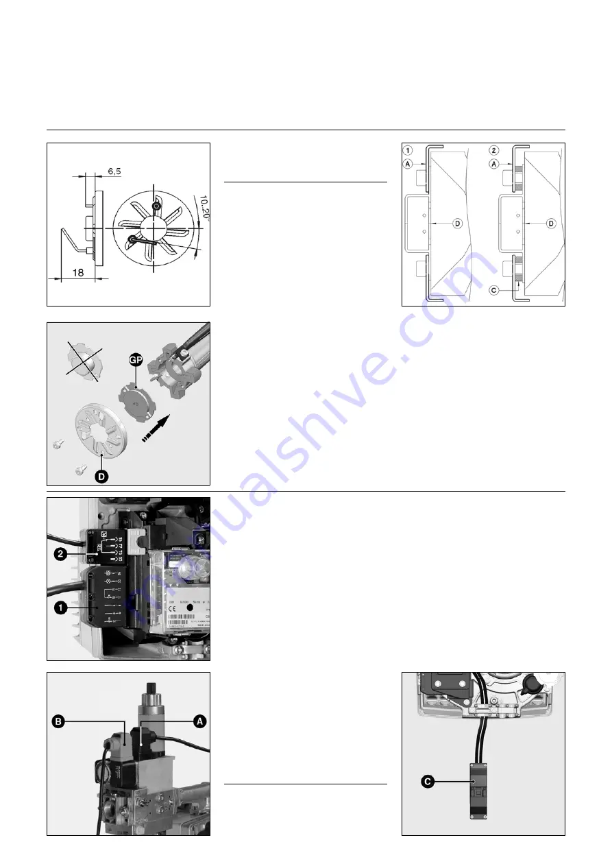
Compact burner unit electrical
connection
• The compact gas unit is connected via
two connectors prewired to the burner
terminal block.
• Connect connectors
A
and
B
to the
corresponding equipment connectors
on the compact gas unit and secure
using the screws.
Connector
A
: Gas pressostat
Connector
B
: gas valve
Main gas safety valve (Switzerland)
electrical connection
• The gas safety valve (installation site)
is located on connector
C
.


