06/2011 - Art. Nr. 13 018 118C
36
Function
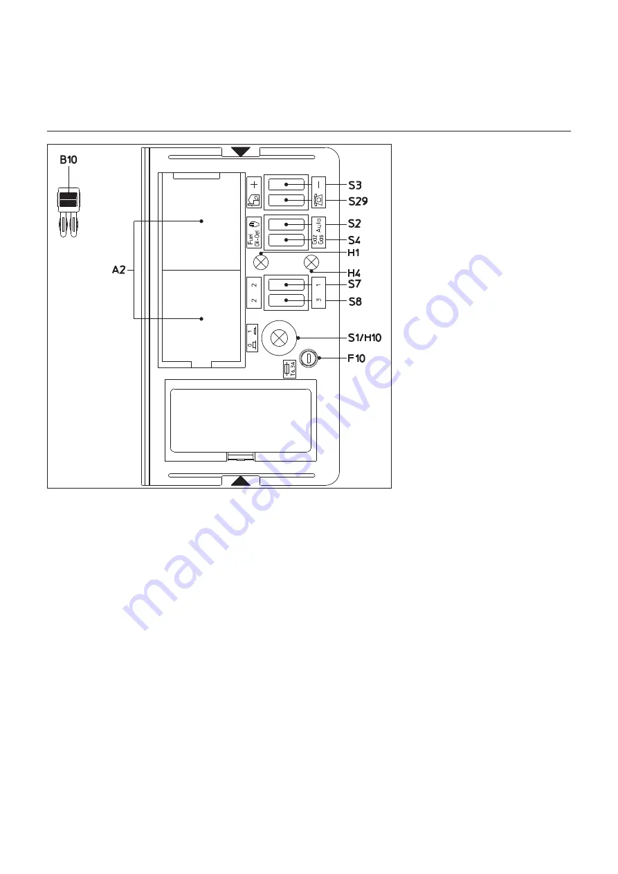
TC control panel
Control panel
All control elements are visible exter-
nally. A removable transparent cover
clipped to the burner cover gives
access to the monitoring and control
elements for setting and operating the
burner.
The control panel also includes two
green diodes that show the fuel being
used and the circuit cut-out.
To detach the lid, press slightly to one
side, or on both sides at the located
sites
xv
, and remove simultaneously.
To replace the cover, locate the two
clips at the appropriate openings and
push in.
Option:
–
RWF 40 three-point regulator fitted
at standardised position.
Function
A2
Standardised installation locations
48x48 or 48x96 mm for the installa-
tion of a power regulator (Option)
B10
Measurement bridge [µA DC] for
cell current, arranged next to the
motor protection
F10
Fuse
H1
Oil operation signal lamp
H4
Gas operation signal lamp
S1
Main switch
0
Off
1
On,
green control bulb
H10
lights up
S2
Selection of the power regulation
K
Manual mode
Auto
On-site automatic mode
S3
Is connected to
S29
J
- S2
K
+/-
power increase/decrease
S4
Fuel selector switch Oil/Gas
Connected to
S29
J
- S2
K
S7-S8
Connected to
S29
J
- S2
K
S7.1+S.8.2
1st stage Oil
S7.2+S.8.2
2nd stage Oil
S7.2+S.8.3
3rd stage Oil
S7.1+S.8.3
3rd stage Oil
S29
Selector switch of operating
location
J
On-site operation
H
Remote operation (Option)
SA1
Combustion control unit display
Troubleshooting key - Fault light
(position on combustion control unit)
m
N.B.
:
The main switch of the control panel
only switches the control voltage. Before
working in the control area of the burner,
disconnect it fully from the mains, incl.
burner motor AC connection.
Summary of Contents for VGL 06.1200 DP
Page 26: ......


