Euro-500TX Handy
© Elcom, s. r. o.
Service manual
40
Euro-500TX Handy
© Elcom, s. r. o.
Service manual
41
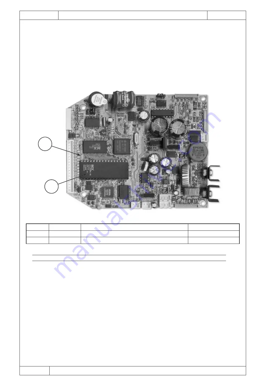
4. Carefully remove the EPROM chip from its socket (take care not to short-circuit or damage me-
chanically any of its pins – this can cause data loss).
5. Carefully inset the new EPROM chip into the socket in correct position. Take care not to damage
the chip mechanically or by static. As the chip is inset, watch for proper fitting of its pins into their
socket contacts.
6. Plug all the connectors into the main PCB.
7. Assemble all the covers back (chapter 4.1)
8. Perform all the ECR tests.
Note: If the EPROM is reinstalled due the version change, it is necessary to erase SRAM using the JP1
jumper (chapter 4.7).
4.7 Defective SRAM replacement or replacing the SRAM to higher capacity
1. Turn the ECR off and make sure that the external power supply is disconnected.
2. Pull out the middle cover and separate the front cover from the bottom one (chapter 4.1).
3. Unplug all the connectors from the main PCB.
4. Detour voltage from the SRAM using the JP1 jumper. Jumper is to be placed to the position
nearer the NiCd accumulator.
5. Take out the SRAM chip from the main PCB.
6. Carefully solder new SRAM. Incorrect placement of SRAM chip can damage the chip. Removal
of damaged SRAM and soldering of a new one shall be performed only by authorised service
centre.
7. Place the JP1 jumper back to its original position farther from the NiCd accumulator.
8. In case of SRAM expansion to 512 kB it is necessary to solder out the R26 resistor 10k and to
solder resistor 0k into position R25.
9. Plug all the connectors back into the main PCB.
10. Assemble all the covers back (chapter 4.1).
11. Turn the ECR on.
12. The ECR initialises itself automatically.
13. Perform all the ECR tests.
Index
Quantity
Description
Code
1
1
EPROM memory
M170072
2
1
PCB Euro 500TX Handy MB v1.2
1
2
Fig. 4.10 EPROM chip on the main PCB
Tab. 4.7 Table of shown parts


