background image

33

en

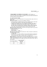
DISP
(DISPLAY)

VIEW

Choose between RF wave, RECT (rectified) wave, BSCAN 
(cross section), and DIGITS (large digits) views.

DELAY
(B-START)

Adjust where the left side of the display window starts 
according to thickness, in inches or millimetres.

RANGE
(B-DEPTH)

Set the overall depth of the viewable measurement area. It 
functions a lot like a zoom on a camera.

B-SCAN 
SPEED

Adjusts the scroll speed of the B-Scan.
Scale is 0-10 where 10 is the fastest. Default setting: 6.

UNITS

Toggle between Metric (millimetres) or English (inches) 
units.

CONTRAST

Adjusts the brightness of the display.
Scale is 0-20 where 20 is the constrast.

RECT WAVE

Toggles between an outlined or filled view option when the 
display setting is in RECT (rectified) wave mode. 

DETECT MARK

Choose the format of the vertical line on the RF and RECT 
measurement screens which shows the detection point:
Line, Box, Dots, None.

TUNE

MEASURE 
MODE

Choose which measurement mode to use.

POLARITY
(ABDL only)

The gauge operates on a zero crossing detection principle.
This feature toggles which stroke of the cycle the crossing
detection uses, either positive or negative.

PULSE
(ABDL only)

Your gauge has adjustable pulse width for both high 
penetration and resolution applications. The pulse width 
refers to the duration of time the pulser is on. The options 
are SPIKE, THIN, and WIDE.

PULSER VOLT
(ABDL only)

Provides a 50 V cut/boost to the pulser. The standard setting
is 150 V. Provides greater penetration for difficult material
types, or increased resolution on noisy materials.

ATTN
(ABDL only)

Provides 20dB attenuation or 20dB amplification of signal
strength. Provides increased or decreased amplifier
strength by a power of 10 (20dB). This attenuation value is
added to the gain value. Therefore, if the attenuator is
increased to 20dB, this value is added to the value of the
gain setting.

GAIN

Increases or decreases the overall amplitude of the signal.
Gain is similar to the volume control on a stereo receiver.

AGC

When operating in E-E or E-EV mode, the gauge adjusts the
gain automatically. Alternatively, the AGC can be manually
controlled.

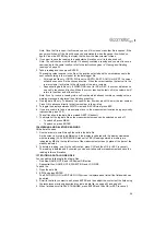
GT1
(GATE 1)

(ABDL only)

GATE1

Sets the start of the gate, according to time/distance.

GATE1 WIDTH

Sets the overall width of the gate, in terms of distance, from
the starting value of Gate1

THRESHOLD1

Sets the sensitivity level of Gate1. The amplitude of the
signal must reach or exceed this threshold level before a
measurement is detected.

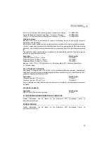
Menu

Function

Description

Summary of Contents for CG100ABDL

Page 1: ...0 en Model CG100ABDL CG100BDL CG100B Corrosion Gauge Operating Instructions...

Page 2: ...ter Limited Edge Lane Manchester M43 6BU United Kingdom Material Safety Data Sheets for the ultrasonic couplant supplied with the instrument and available as an accessory are available to download via...

Page 3: ...easurement technique 18 11 Measurement Options 18 12 Flaw Mode CG100ABDL gauges only 21 13 Measurement Recording your Readings CG100DL gauges only 22 14 Gauge Setups 25 15 Data Transfer Software 26 16...

Page 4: ...asured The CG100 series also include a data logging memory facility which allows readings to be stored in batches before being downloaded to a computer 1 1 STANDARDS Your gauge can be used in accordan...

Page 5: ...roups These tab groups then contain sub menu items or functions Clears a measurement from a log file cell location or set obstruct and back space in an Alpha Edit Box Press to start taking measurement...

Page 6: ...the material being measured The transducer connects to the gauge via the attached cable and two coaxial connectors When using transducers manufactured by Elcometer the orientation of the dual coaxial...

Page 7: ...isplayed in English Spanish and German 1 Select MENU SET LANGUAGE and adjust 5 THE MEASUREMENT SCREEN Your gauge has up to four types of measurement screen A Scan Waveform RF CG100ABDL gauges only A S...

Page 8: ...ity of the material under the transducer type depends upon measurement view D Units The current measurement units Metric English E Feature Status Bar Indicates the features currently enabled and in us...

Page 9: ...splay provides a cross sectional view of the material being tested In this example the top or accessible side of the material is represented as 0 00mm and the bottom or blind surface at 25 4mm This mo...

Page 10: ...ly 25mm and an operator was assessing for corrosion on this wall they might set the DELAY to 10mm and the range to 30mm to fit as much relevant information on the display as possible B START and B DEP...

Page 11: ...Digits Edit Box 2 Press OK to set the value 3 Adjust to suit the measurement application 4 Press MEAS to return to the measurement screen 5 9 THRESHOLD CG100ABDL gauges only The threshold is the leve...

Page 12: ...asing decreasing temperature gradient in the test material Note Rough surface conditions can have an effect on the overall accuracy in this mode If the surface condition is in question the pulse echo...

Page 13: ...croll through the transducer list until the cor rect type is highlighted and then press ENTER 3 Press OK to overwrite the existing transducer type with the newly selected transducer type 4 Your gauge...

Page 14: ...d free of any debris 3 Apply a drop of couplant on the transducer and place the transducer as shown in diagram Note Disregard the value displayed it is not important What is important is accurately pe...

Page 15: ...m s 1 Known Thickness calibration A sample of the material to be inspected is measured using alternative means and then used to calibrate the gauge One Point calibration is the simplest and most comm...

Page 16: ...PT 3 Press ENTER to display the Digits Edit Box 4 Adjust to match the material thickness 5 Press OK to calculate the velocity and return to the measurement screen or ESC to cancel Note Place the trans...

Page 17: ...that the reading is stable and the repeatability indicator in the top left corner of the display is fully lit and stable 3 Select EMNU CAL COATING 1PT function 4 Press ENTER to display the Digits Edit...

Page 18: ...Setting Type Of on page 16 Select the correct measurement mode P E PECT PETP E E E EV CT see Measurement Modes on page 10 Set the zero point of the transducer see Transducer Zeroing on page 12 and Tr...

Page 19: ...1 Press MENU GT1 GT2 or GT3 menu and then highlight the setting you wish to adjust 2 Adjust to suit the measurement application 3 Press OK to set the value and return to the menu screen or ESC to can...

Page 20: ...u can choose to activate both or just one of these values depending on your requirements To enable disable Alarm Mode 1 Select MENU UTIL ALARM 2 Use LEFT and RIGHT to toggle the ALARM on off audible 3...

Page 21: ...to achieve optimal results Low frequency applications where more penetration is a requirement may require the Thin or Wide settings offering increased penetration The variety of transducer frequencie...

Page 22: ...play to reset to zero press CLR 4 Press MEAS to return to the measurement screen Note When flaw mode is activated a transducer delay will still be configured from the previously loaded transducer This...

Page 23: ...nd end ID are entered into the gauge and the log created the gauge automatically generates all the identifiers within that range Data logger filename character setsAny combination of the following cha...

Page 24: ...ENTER and then OK to confirm The measurement grid is now displayed along with the grid name on screen 13 3 CREATING A NEW DATA LOGGER FILE SEQUENTIAL FORMAT 1 To create a SEQ log data file 2 Scroll to...

Page 25: ...r Press OK to advance directly to that row number in the grid log 5 To toggle the display between DIGITS view and B SCAN view press ESC 6 If you are unable to take a measurement due to the measurement...

Page 26: ...type Gain setting Scan mode setting Alarm settings Differential settings Display type setting As well as storing the setups in your gauge you can also store the setups on a computer and transfer them...

Page 27: ...A SAVED SETUP This option deletes a setup file from your gauge for example if it is no longer needed 1 Press MENU scroll to the SET menu and then highlight the DELETE function 2 Press ENTER to display...

Page 28: ...selected 3 Once the Backup or Restore function has been completed press MEAS once to return to the menu items or twice to return to the measurement mode 16 STORAGE Your gauge has a Liquid Crystal Disp...

Page 29: ...n s to 0 5510 in s Weight including batteries 380 g 13 5 oz Dimensions W x H x D 63 5 mm x 165 mm x 31 5 mm 2 5 x 6 5 x 1 24 Gauge Operating Tempera ture 10 C to 60 C 14 F to 140 F Case Aluminium case...

Page 30: ...rights which may vary from country to country state to state or province to province 19 2 OBTAINING SERVICE DURING WARRANTY PERIOD If your hardware should fail during the warranty period contact Elco...

Page 31: ...alibration Block 8 Step 1 8mm TW 24005 Calibration Block 10 Step 2 20mm TW 24006 Calibration Block 10 Step 2 5 25mm TW 24007 Replace with S1018 1018 Steel Block A Aluminium Block SS Stainless Steel Bl...

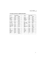
Page 32: ...5232 0 206 PVC 2388 0 094 Copper 4674 0 184 Quartz Glass 5639 0 222 Epoxy Resin 2540 0 100 Approx Rubber Vulcan ised 2311 0 091 German Silver 4750 0 187 Silver 3607 0 142 Glass Crown 5664 0 223 Steel...

Page 33: ...ith single element angle beam transducers and used as a general prove up flaw inspection mode CAL CALIBRATION MAT Select the material velocity from a chart of basic material types when a known sample...

Page 34: ...only Your gauge has adjustable pulse width for both high penetration and resolution applications The pulse width refers to the duration of time the pulser is on The options are SPIKE THIN and WIDE PU...

Page 35: ...the signal must reach or exceed this threshold level before a measurement is detected SET SETUP OPEN Displays a list of factory and user defined setups currently stored in memory These setups can be...

Page 36: ...larm will sound DIFFERENTIAL Sets a nominal value and your gauge will display the dif ference from this nominal value XFER TRANSFER BACKUP SETUPS Allows you to backup the setups currently stored in yo...

Page 37: ...EV 11 F Flaw Mode 21 G Gates 10 Gauge Setups 26 Grid Log 24 H High Speed Scan 20 K Known Material Calibration 15 M Measurement Modes 10 Measurement Procedure 18 Measurement Screens 7 Measuring Coatin...

Page 38: ...37 Transducer delay line 18 Tuning 21 Two Point Calibration 15 V Viewable Range 9 Viewing Readings 25 W Wide Pulse 21 Z Zero Coating 14 Zeroing 13...

Reviews: