- 6 -
3.2 Operation
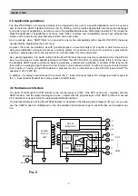
The Mux2700 HSM module implements HART protocol commands and acts as a gateway device between the
Maintenance Workstation (MW) and the field devices. It responds to commands received from the MW (RS-485
interface) as a slave device and issues commands to the HART slaves (field channels) acting as either a Primary
or Secondary Master (according to the HART specification).
A modified version of the HART protocol was implemented on the RS-485 physical layer to obtain a fast and relia-
ble communication with the Maintenance Workstation. In this way, standard HART messages can be used by the
MW for an effective, seamless integration of field devices from different manufacturers.
The Mux2700 can continuously poll each connected field device the get the specified primary (or secondary) HART
variable, automatically updating the internal data-base. This is called
scan
operation, and can be enabled or disa-
bled by the Maintenance Workstation (the Mux are factory set in the “Scan-Off” condition). When in the “Scan-On”
mode, the MW can generate a warning message whenever a field device stop communicating (e.g. because it is
disconnected from the loop).
At power-up, the Mux2700 always performs a
locate
activity, that is to say, it polls all the 32 channels to find any
connected – and communicating – field device and to rebuild the required, internal access tables. The locate acti-
vity can be started also by the Maintenance Workstation, and this is usually required to be able to communicate
with a new field device connected to the Mux after power-up. The locate time can range from 15 to 60 seconds,
depending on the specified retry counts (the Mux are factory set with a retry count = 3, resulting in around one
minute of locate time).
In addition to providing access to the HART-capable field instruments, the Mux2700 module is itself, in all respect,
an HART device with parameters and internal functions available to the user (e.g. Tag, Description and unique DIN
– Device Identification Number).
3.3 LED indications
The information provided by the Mux 2700 LED (mounted at the panel front) is summarised in the following table:
3.4 Power-up sequence
In the following, the normal Mux 2700 power-up sequence is described. This is always the standard power-up
behaviour, unless SW8 (at the panel front) is set into the Test position.
•
Immediately after power-up, the Green LED goes immediately On.
•
An internal
self-test
is then performed and, if any problem is detected, the Red LED goes fixed On (on some
Mux versions, the Green LED could blink during self-test).
•
The Yellow LED then start blinking, indicating that the Mux 2700 is performing the
locate
activity, that can last
up to around one minute (N.B. when the field multi-drop option is available and active, the locate time could be
up to15 minutes).
•
The Yellow LED should then go Off, unless the
scan
operation is enabled or the Maintenance Workstation is
directly communicating with a field device.
IM-ENG-116/GB
Colour
Name
Function
Yellow
HART TX
ongoing HART communication with field devices
Green
PWR ON
supply indicator (can blink at power-up)
Red
FAULT
internal fault indication (power-up detection only)


