background image

Sieve Shaker for 200mm or 8 inch and 300mm or 12 inch diameter sieves  
80-0200 


9907X0058 Issue 2 


This product may be operated through a standard 13 amp socket outlet when fitted 
with an appropriate 3 pin plug fused in accordance with the label. 

The power cable is coded as follows: 

Brown wire 

Live or Power 

Blue wire 

Neutral 

Green/Yellow wire 

Earth or Ground 

Important Note

 :

 This equipment must be correctly grounded (earthed). 

3.1.2


Portable Appliance Tests (PAT) 

All ELE designed products are tested for electrical safety prior to sale. 

Organisations have an obligation to ensure equipment is maintained and is safe for 
use. Regular PAT testing is one means of ensuring equipment continues to be 
electrically safe. 

Important Note

 :   Do not connect PAT leads to sensitive components such as 

PCBs, control switches, etc. 

 
DO NOT FLASH TEST ELECTRONIC EQUIPMENT. 

If in doubt as to the most suitable ground connection point (which will usually 
be a screw or metallic part) then contact ELE Service Department for 
assistance.


3.2 

CAUTION :  

This product is heavy and care must be taken when lifting it. Do not 

attempt to lift it with only one person. Use sufficient resources to lift it safely in order 
to avoid injury or damage to the equipment. 

3.3 

CAUTION :  

Do not power up or run the sieve shaker before reading and fully 

understanding Section 4 relating to the use of the controls for this product. 

3.4 

CAUTION :  

Ensure all appropriate measures are taken to protect the operator from 

excessive noise by using good quality industrial ear defenders. 

3.5 

Important Note :


Do not run the sieve shaker empty as this could seriously damage 

the vibrating system inside the shaker and invalidate the warranty for this product. 

3.6 

Position the shaker on a suitable level rigid surface. It is important that the shaker is 
on a level surface ensuring the even distribution of the sample over the sieves during 
the sieving process. 

3.6.1  Place the four nuts supplied onto the threaded rods, two above and two below the 

vibrating base unit of the shaker (C). Finally tighten the nuts to lock the two threaded 
rods in position to the vibrating base unit.


Controls 

4.1 

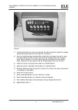
The sieve shaker has the user controls located in the main control module. 

4.2 

Mains power switch is located on the right hand side of the main control module and 
the OFF position is marked ( O ) and the ON is marked ( I ). 

4.3 

Any changes made to the various user definable options will be stored in memory 
when the shaker is switched off. 

4.4 

For a full guide to the front panel controls and display see Figures 2 and 3. 


Summary of Contents for SIEVE-TRONIC

Page 1: ...d Bedfordshire LU7 4WG England phone 44 0 1525 249200 fax 44 0 1525 249249 email ele eleint co uk http www ele com ELE International a division of Hach Lange Ltd Distributor ELE International Soiltest Product Division PO Box 389 Loveland CO 80539 USA phone 1 800 323 1242 fax 1 970 663 9781 email soiltest eleusa com http www eleusa com In the interests of improving and updating its equipment ELE re...

Page 2: ...00mm or 12 inch diameter sieves 80 0200 2 9907X0058 Issue 2 Contents Section Page 1 Introduction 3 2 Specification 4 3 Installation 4 4 Controls 5 5 Operation 7 6 Maintenance 8 7 Trouble Shooting 8 8 Spares and Accessories 8 WEEE Directive ...

Page 3: ... to the material being sieved so that it makes a slow progression over the surface of the sieve At the same time a rapid vertical movement agitates the sample which assists in clearing the apertures to minimise blinding of sieve apertures Sieving times are fully variable from 1 to 999 minutes The shaker also has an intermittent time mode where the sieving process can be punctuated with rest period...

Page 4: ...atements DANGER Indicates a potentially or imminently hazardous situation which if not avoided could result in death or serious injury CAUTION Indicates a potentially hazardous situation that may result in minor or moderate injury Important Note Information that requires special emphasis Note Information that supplements points in the main text 2 Specification Dimensions mm Sieve shaker Control mo...

Page 5: ...afely in order to avoid injury or damage to the equipment 3 3 CAUTION Do not power up or run the sieve shaker before reading and fully understanding Section 4 relating to the use of the controls for this product 3 4 CAUTION Ensure all appropriate measures are taken to protect the operator from excessive noise by using good quality industrial ear defenders 3 5 Important Note Do not run the sieve sh...

Page 6: ...h will be flashing To exit the option press the 2 button until the display stops flashing The main options can be changed again with the 1 button 3 Allows the user to increase values when in a selected option 4 Allows the user to decrease values when in a selected option 5 Switches ON the sieving process when ready This button can only be used when L is showing in the display 6 Stops the sieving p...

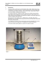
Page 7: ...creased As the digit changes the vibrating power will change accordingly 5 Operation 5 1 Apply power to the sieve shaker by switching the mains switch on the control module to I 5 2 Sieve stacking see Figure 1 Place the receiver centrally into the appropriate recess in the lower vibrating location plate Stack the required number of sieves on top of the receiver Place the sample in the top sieve an...

Page 8: ...lution Under no circumstances should solvents be used as they will damage the paint finish 6 2 If at any time the shaker makes a strange noise which cannot be rectified by reducing the vibration intensity contact ELE for further information Do not run the sieve shaker in this state as serious damage to the internal mechanisms could occur 7 Trouble Shooting DANGER This work must only be carried out...

Page 9: ...DIRECTIVE ON WASTE ELECTRICAL ELECTRONIC EQUIPMENT WEEE ...

Page 10: ......

Reviews: