


11
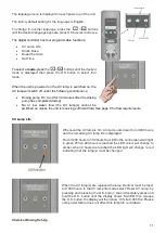
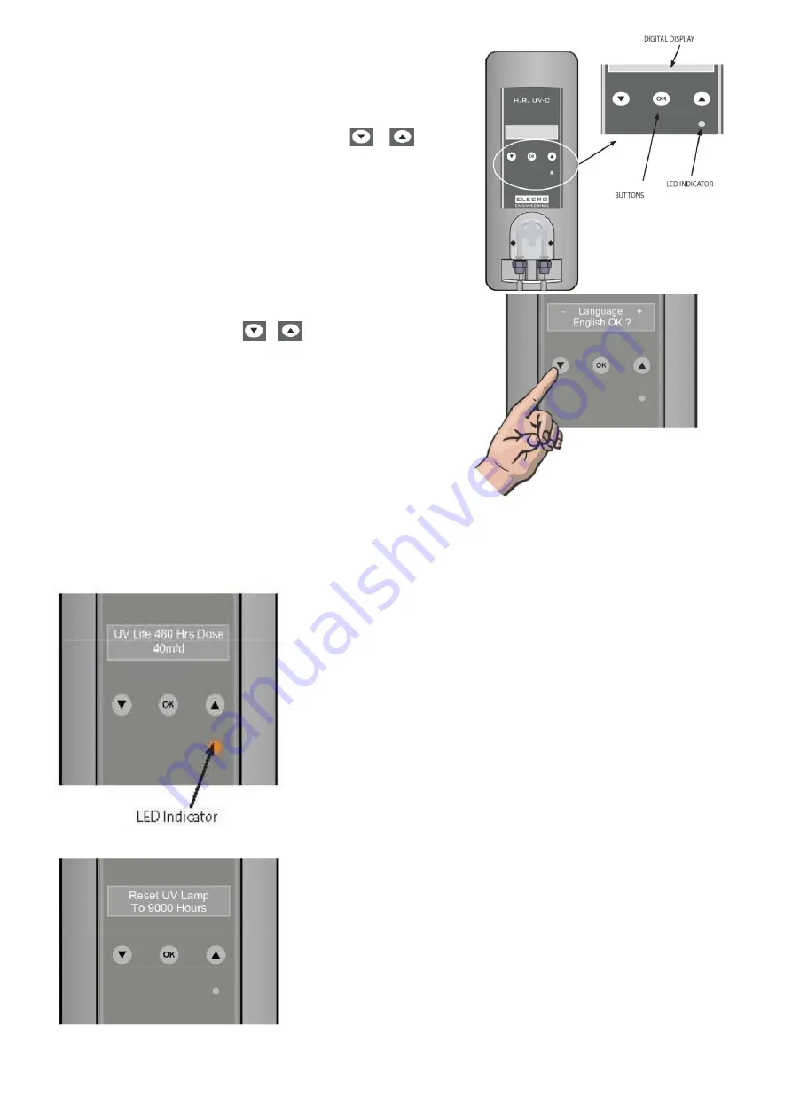
The language menu is displayed on each power up of the unit.
The factory default setting for the language is English.
To change to another language, press the
/
buttons
until the desired language appears, press OK to select and save.
The digital controller has four programmable functions:
•
UV Lamp Life
•
Shock Dose
•
Dose Chemical
•
Set Time
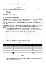
To select a
mode,
press
the
/
buttons until the desired
mode is displayed then press the OK button to select that
mode.
When the unit is powered on the UV lamp is switched on, the
UV lamp will switch off under the following conditions i.e.
•
Dosing pump ‘On’ (and for 30 minutes after the dosing
pump has completed dosing)
•
No or low water flow (the UV lamp(s) cannot be
switched on unless the unit is receiving sufficient flow) See page 9 for flow requirements.
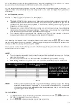
UV Lamp Life
Whenever the UV lamp is ‘On’ a timer counts down from 9,000 hours
and the remaining UV lamp life is displayed.
From 9,000 hours to 500 hours the LED in the control panel will light
in green. When 499 hours is reached the LED colour will change to
amber, when 0 hours are reached the LED light will change to red
indicating that the lamp(s) must be changed
When the UV lamp(s) are replaced the lamp life timer must be reset
to 9,000 hours. In the UV lamp life mode select ‘Reset UV Lamp’ by
pressing and releasing the O.K. button, then immediately press and
hold the O.K. button until the display shows ‘SAVED’ then release
the O.K. button, the display will then show ‘UV Life 9,000 Hrs’ Please
note power failure does not affect this lamp life countdown.
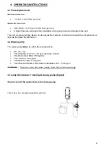
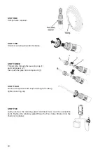
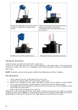
Chemical Dosing Set-Up
Summary of Contents for H.R.UV-C SPA-PRO
Page 1: ...H R UV C SPA PRO Installation and Operating Manual HRP 30 SPA ENGLISH...
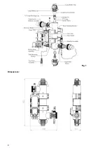
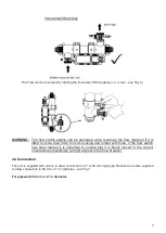
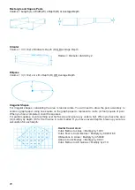
Page 4: ...4 Fig 1 Dimensions...
Page 21: ...21 Notes...
Page 23: ...23...


