


14
•
NOTE:
the time must be entered in the 24-Hour format.
•
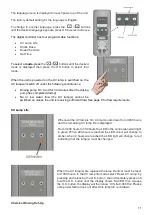
The display will now revert to showing the UV lamp life remaining and the current time.
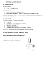
Shock Dose
The shock dose feature enables the operator to shock dose the pool immediately with a chosen volume
of the dispensing chemical. This may be necessary following heavy use of the pool or a change of water
conditions.
To activate the shock dose feature, use the
/
buttons
to scroll until ‘SHOCK DOES’ is displayed,
press the ‘O.K’ button.
Using the
/
buttons select the volume (ml/millilitres) that you would like to shock dose the pool
with. When the correct value is shown, press the
’O.K’ button to confirm. The display will show ‘SAVED’
and the shock dose will begin immediately.
NOTE:
The shock dose will only begin if the main filtration pump is operational.
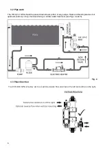
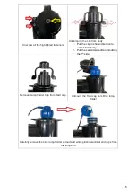
5. MAINTENANCE
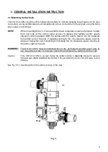
To avoid any water leaks and optimum performance annual maintenance of the UV steriliser is
essential. Failure to do so could result in damage to the product and significant drop in efficiency.
Annual maintenance includes:
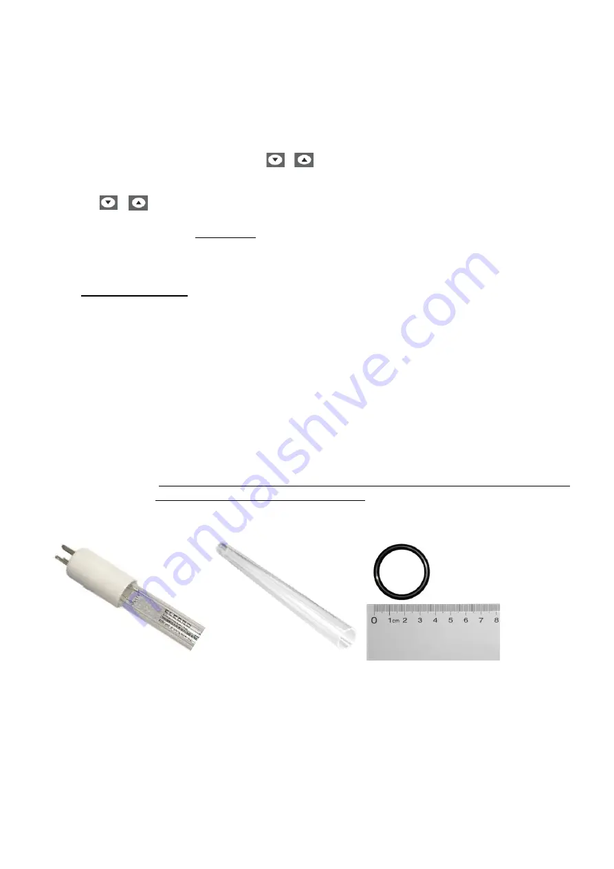
•
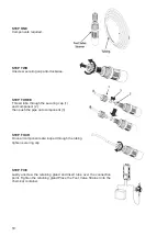
Changing of lamps(s) if necessary. Fig. 1.
•
Inspection and cleaning of quartz sleeve. Replace if any cracks are discovered. Fig. 2.
•
Replacing all O-rings. Fig. 3.
•
Replacing lamp connectors (white plastic insert inside the blue bulb cap) if corroded, wet,
damaged or overheated. Fig. 4.
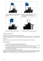
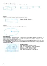
5.1 Essential parts to carry out annual maintenance including our reference codes
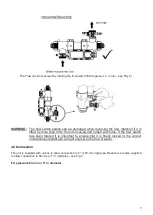
WARNING:
Before performing any maintenance isolate from the main power supply, turn
off circulation pump and drain the unit.
SP-UV-LAMP-30-AM
SP-UV-QS-30
SP-UV-ORS
Fig. 1
Fig. 2
Fig. 3
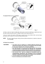
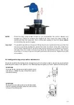
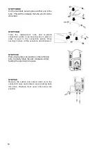
5.2 Lamp replacement and quartz sleeve cleaning
Removing the lamp and quartz sleeve
Summary of Contents for H.R.UV-C SPA-PRO
Page 1: ...H R UV C SPA PRO Installation and Operating Manual HRP 30 SPA ENGLISH...
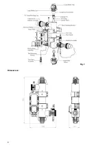
Page 4: ...4 Fig 1 Dimensions...
Page 21: ...21 Notes...
Page 23: ...23...