


17
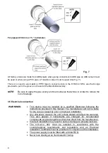
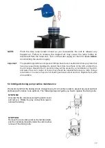
NOTE:
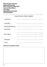
Pinch the blue lamp holder shroud as you reassemble the unit to release any
trapped air. Failure to release the trapped air may cause the lamp holder to
disconnect from the lamp end. Turn on the water supply to check for leaks before
reconnecting the electric supply.
Important:
The plastic body and blue compression fittings have been manufactured from polymers that
have been specifically stabilised to protect them from the effects of the UVC emitted from
the UV lamps. Despite this UV protection they will be eroded by a combination of the UVC
and water flow. As a matter of course they should be inspected whenever a lamp change
is carried out, to ensure they are not showing excessive wear and tear. Replacement parts
are available.
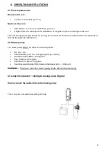
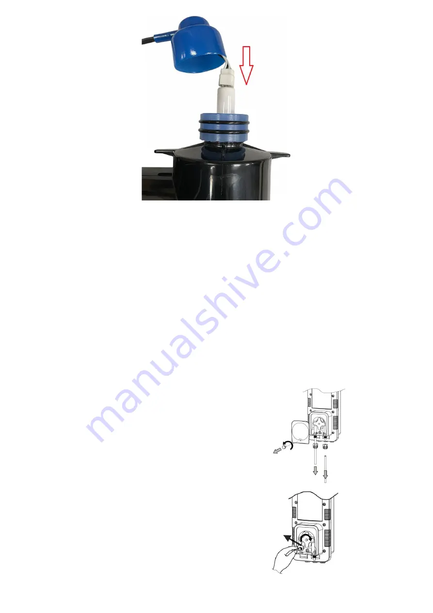
5.3 Intelligent dosing pump routine maintenance
We recommend that the dosing tube is changed every 6-12 months in order to prevent any wear and tear
and keep performance to an optimum. The following steps will guide you how to replace the dosing tube:
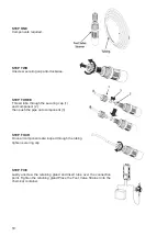
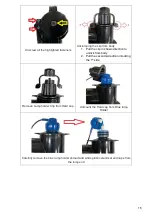
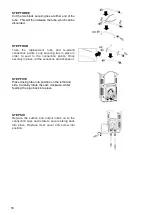
STEP ONE
Unscrew the two screws securing the plastic cover
and remove. Rotate the grey connections caps to
release the tubing.
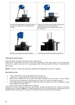
STEP TWO
Remove the connection point on the left-hand side,
and then carefully manually rotate the cam to allow
remove of the dosing tube.
Summary of Contents for H.R.UV-C SPA-PRO
Page 1: ...H R UV C SPA PRO Installation and Operating Manual HRP 30 SPA ENGLISH...
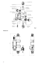
Page 4: ...4 Fig 1 Dimensions...
Page 21: ...21 Notes...
Page 23: ...23...


