background image


Introduction 

 
Thank  you  for  purchasing  the  H.R.UV-C  SPA  pool  sanitising  system,  the  latest  in  high  reflection  UV 
technology, manufactured to the highest standards in England. 
 
To ensure years of trouble-free service, please 

read and follow

 these instructions for proper installation, 

maintenance and use. 

Incorrect installation will affect your warranty. 


Please retain this manual for future reference. 


1.  IMPORTANT SAFETY INSTRUCTIONS 


WARNINGS: 

  Read the maintenance instructions before opening the appliance. 

  Do not operate the ultraviolet-C emitter when it is removed from the appliance enclosure.  

  Unintended use of  the appliance or damage to the housing may result in the escape of 

dangerous ultraviolet-C radiation.  ultraviolet-C radiation may, even in  little doses,  cause 
harm to the eyes and skin.  

  This unit must be earthed.  

  Power must be supplied through a Residual Current Device (RCD) with a rated residual 

operating current not exceeding 30mA 

  Do not run this unit dry 

  Do not cover this unit 

  The unit must not be submerged in water 

  Carefully examine the unit after installation. It should not be powered on if there is water 

on any parts not intended to be wet 

  If the unit shows any sign of water leakage immediately disconnect power supply 

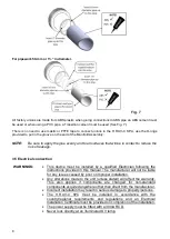
  If the quartz sleeve is cracked, replace it immediately 

  To avoid injuries young children should never be allowed near UV sanitizer 

  Failure  to  disconnect  the  power  from  the  UV  sterilizer  and  pump  before  servicing  or 

maintenance could result in personal injury or property damage. 
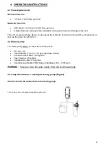
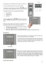
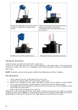
 

2.  PRODUCT OVERVIEW 


The 

H.R.UV-C SPA 

is available in 30W single tube format, supplied complete with flow switch and 

either an analogue lamp life indicator and reset switch, or digital lamp life countdown with intelligent 
dosing pump.


Summary of Contents for H.R.UV-C SPA-PRO

Page 1: ...H R UV C SPA PRO Installation and Operating Manual HRP 30 SPA ENGLISH...

Page 2: ...ATING INSTRUCTIONS 9 4 1 Flow requirements 9 4 2 Water quality 9 4 3 Lamp life indicator intelligent dosing pump Digital 9 5 MAINTENANCE 14 5 1 Essential parts to carry out annual maintenance includin...

Page 3: ...o the eyes and skin This unit must be earthed Power must be supplied through a Residual Current Device RCD with a rated residual operating current not exceeding 30mA Do not run this unit dry Do not co...

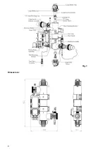
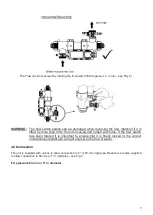
Page 4: ...4 Fig 1 Dimensions...

Page 5: ...uired Both the lamps and the quartz sleeve can be replaced from either end of the unit if installing vertically the 1m clearance space must be above or below the unit if installing horizontally the 1m...

Page 6: ...fter of any pumps filters and heating devices but upstream before of any chemical dosing or similar water treatment see Figs 4 and 5 Fig 4 3 3 Flow direction The H R UV C SPA is factory set to accept...

Page 7: ...housing and turned with force If the flow switch has been rotated it is important to ensure that it is finally locked in the correct orientation perpendicular at right angles to the flow of water 3 4...

Page 8: ...be installed by a qualified Electrician following the instructions provided in this manual The manufacturer will not be liable for any issues caused by poor or improper installation Any alterations ma...

Page 9: ...work as soon as the power is switched on 4 2 Water quality The water quality MUST be within the following limits PH 6 8 8 0 Total Alkalinity TA 80 140 ppm parts per million Chloride Content MAX 150 mg...

Page 10: ...ring cap 1 and component 2 then push the pipe onto component 3 STEP FOUR Once all components are looped through the tubing tighten securing cap STEP FIVE Lastly unscrew the retaining gland and insert...

Page 11: ...p s cannot be switched on unless the unit is receiving sufficient flow See page 9 for flow requirements UV Lamp Life Whenever the UV lamp is On a timer counts down from 9 000 hours and the remaining U...

Page 12: ...this time every day 24 Hours NOTE The time selected must be at a time when the main filtration pump will be running Once the desired time has been selected press the O K button and the display will t...

Page 13: ...n Part 1 the display will show CL DOSE using the buttons select the correct dosage volume in ml millilitres Once the correct dosage volume is displayed press the O K button to confirm the display will...

Page 14: ...e shock dose will only begin if the main filtration pump is operational 5 MAINTENANCE To avoid any water leaks and optimum performance annual maintenance of the UV steriliser is essential Failure to d...

Page 15: ...e clip in shown direction to unlock from body 2 Pull the second side after unlocking the 1st side Remove Lamp holder Clip from Hard cap Unmount the Hard cap from Blue lamp Holder Carefully remove the...

Page 16: ...ill limit the effectiveness of the UV lamp s Assembly process Firstly slide the clean dry quartz glass sleeve into the unit Locate the O rings carefully on the ends of the quartz sleeve Make sure the...

Page 17: ...a combination of the UVC and water flow As a matter of course they should be inspected whenever a lamp change is carried out to ensure they are not showing excessive wear and tear Replacement parts a...

Page 18: ...ies in place in order to seal to the connection points Once securely in place cut the excess tie and dispose of STEP FIVE Place dosing tube into position on the left hand side Carefully rotate the cam...

Page 19: ...ainst faulty workmanship and materials for two years within Europe one year outside Europe The manufacturer will replace or repair at its discretion any faulty units or components returned to the Comp...

Page 20: ...ne square on the graph paper to represent a metre or foot square of pool When you have completed count the squares For partial squares count anything over half as one and ignore any under a half When...

Page 21: ...21 Notes...

Page 22: ...Hertfordshire SG1 2BH United Kingdom __________________________________________________________________________________ Customer Information ATTACH TO HEATER Company Name Contact Name Daytime Telepho...

Page 23: ...23...

Page 24: ...24 Unit 11 Gunnels Wood Park Stevenage Herts SG1 2BH Sales elecro co uk www elecro co uk 44 0 1438 749474 Copyright MANE321 EN H R UV C SPA PRO Manual V1 29 09 2021 Elecro...

Reviews: