12-29
CONTROL SYSTEM
SM DELTA 1-E.0 GB
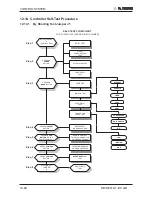
12.14.2
By Remote Control Settings:
a.
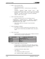
1: TURNING ON THE POWER.
Turn ON the power, make sure that the unit is in operation.
b.
STEP 2 : ENABLE SELF-TEST MODE
•
Use the remote control to send the first settings to display / indoor unit
HEAT mode, HIGH IFAN, set temperature to 16
ºC
,
no I-FEEL Sleep or
any other timer settings are needed.
•
Cover the IR transmitter components in the remote control so that it will
not transmit the signals to the indoor unit display.
•
Use the remote control to send the second settings to display / indoor unit
COOL mode, LOW IFAN, no I-FEEL Sleep or any other timer settings.
•
Uncover the remote control IR transmitter and change the temperature
settings. If the display/indoor unit receive the settings properly the
following steps will start:
c. STEP 3: MODEL SETTING CONFIRMATION
•
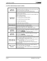
The STAND-BY and COOL LEDS will indicate the operation mode as
follows:
OPERATION MODE
STAND-BY LED
COOL LED
ST
ON
OFF
RC
OFF
OFF
SH
OFF
ON
RH
ON
ON
•
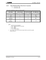
Testing the Model configuration. Selected by the COMP, STAND-BY,
TIMER LEDS and FILTER will indicate the model configuration as follows
(the relevant line for this manual is highlighted):
MODEL
COMP
OPERATE LED
TIMER LED
FILTER LED
WNG
ON
OFF
OFF
OFF
WMN1
ON
ON
OFF
ON
WMN4
OFF
OFF
ON
OFF
WMN2/WHX
OFF
ON
OFF
ON
WMN3
OFF
ON
ON
ON
In this term the step motor will turn to HOME POSITION.
Summary of Contents for DELTA 18
Page 14: ...4 2 OUTLINE DIMENSIONS SM DELTA 1 E 0 GB 4 3 Outdoor Unit OU7 24 OU7 24Z...
Page 21: ...5 7 PERFORMANCE DATA PRESSURE CURVES SM DELTA 1 E 0 GB 5 6 Pressure Curves 5 6 1 Cooling...
Page 22: ...5 8 PERFORMANCE DATA PRESSURE CURVES SM DELTA 1 E 0 GB 5 6 2 Heating...
Page 31: ...8 1 WIRING DIAGRAMS SM DELTA 1 E 0 GB 8 WIRING DIAGRAMS 8 1 Indoor Unit DELTA 18 21 24...
Page 32: ...8 2 WIRING DIAGRAMS SM DELTA 1 E 0 GB 8 2 Outdoor Unit GC 18 1PH R410A...
Page 33: ...8 3 WIRING DIAGRAMS SM DELTA 1 E 0 GB 8 3 Outdoor Unit GC 24 1PH R410A...
Page 34: ...8 4 WIRING DIAGRAMS SM DELTA 1 E 0 GB 8 4 Outdoor Unit OU7 24 1PH R410A...
Page 35: ...8 5 WIRING DIAGRAMS SM DELTA 1 E 0 GB 8 5 Outdoor Unit OU7 24 3PH R410A...
Page 36: ...8 6 WIRING DIAGRAMS SM DELTA 1 E 0 GB 8 6 Outdoor Unit OU7 24Z R410A...
Page 39: ...10 2 REFRIGERATION DIAGRAMS Service Manual ALPHA 10 1 2 DELTA 24 OU7 24 R410A...
Page 40: ...10 3 REFRIGERATION DIAGRAMS SM DELTA 1 E 0 GB 10 1 3 DELTA 24 OU7 24Z R410A...
Page 81: ...14 3 EXPLODED VIEWS AND SPARE PARTS LISTS SM DELTA 1 E 0 GB 14 3 Outdoor Unit GC 18 ST...
Page 83: ...14 5 EXPLODED VIEWS AND SPARE PARTS LISTS SM DELTA 1 E 0 GB 14 5 Outdoor Unit GC 18 RC...
Page 85: ...14 7 EXPLODED VIEWS AND SPARE PARTS LISTS SM DELTA 1 E 0 GB 14 7 Outdoor Unit GC 21 RC...
Page 87: ...14 9 EXPLODED VIEWS AND SPARE PARTS LISTS SM DELTA 1 E 0 GB 14 9 Outdoor Unit GC 21 ST...
Page 89: ...14 11 EXPLODED VIEWS AND SPARE PARTS LISTS SM DELTA 1 E 0 GB 14 11 Outdoor Unit GCN 12 RC...
Page 91: ...14 13 EXPLODED VIEWS AND SPARE PARTS LISTS SM DELTA 1 E 0 GB 14 13 Outdoor Unit GC 24 RC...
Page 93: ...14 15 EXPLODED VIEWS AND SPARE PARTS LISTS SM DELTA 1 E 0 GB 14 15 Outdoor Unit OU7 24 RC 1PH...
Page 95: ...14 17 EXPLODED VIEWS AND SPARE PARTS LISTS SM DELTA 1 E 0 GB 14 17 Outdoor Unit OU7 24 ST 1PH...
Page 99: ...14 21 EXPLODED VIEWS AND SPARE PARTS LISTS SM DELTA 1 E 0 GB 14 21 Outdoor Unit OU7 24 RC 3PH...
Page 101: ...14 23 EXPLODED VIEWS AND SPARE PARTS LISTS SM DELTA 1 E 0 GB 14 23 Outdoor Unit OU7 24 ST 3PH...
Page 106: ...15 4 OPTIONAL ACCESSORIES SM DELTA 1 E 0 GB...
Page 107: ...15 5 OPTIONAL ACCESSORIES SM DELTA 1 E 0 GB...
Page 108: ...15 6 OPTIONAL ACCESSORIES SM DELTA 1 E 0 GB...


