III.
5
Output stage balance/
measurement
Electric Signal MMXV AD
Page 11
Delta Transconductace band Compressor
User Manual
Page 12
IV
Using the system
The next chapters describe
how the machine can be used. Due to the high
amount of controls, compared to other
compressors, the front panel may be a bit
overwhelming, but is actually simple if familiar.
Remember there are three elements: Main, filter
and compressors. The controls for the
compressors are arranged in a matrix. This
matrix is present in the whole front panel design
exept for the filter and main section. The
controls for the filters are divided in two
sections, because there are two crossover
frequency’s. Furthermore all secondary functions
are engraved in red and all controls (besides the
calibration trim-pots) operates the left and the
right channel. As mentioned before, due to the
relative large number of operations and the
axiom; ‘a shorter signal pad is in most cases
better’ the Delta Transconductance band
Compressor uses more than 100 signal relays
and they may give a light ‘clicking’ sound if a
control is used.
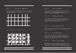
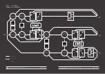
On the next page there is a visual of the block
chain of the machine. In the manual and
on the front panel, the three compressors of the
machine will be defined by high, mid and low
channel. Once the filter is bypassed
this definition
(high, mid, low) it may partially loose it’s meaning, so
for example; bypassing the low pass filter of the
high to mid section resulting in the ‘high’
compressor working over the whole (20hz-
20kHz) frequency range.
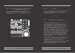
This procedure is equal to the delta mu gain
stages; if an inbalance is measured at pin 7 and
8, the balance needs to be recalibrated. The
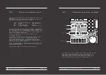
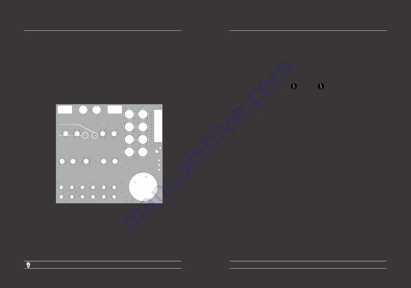
balance pots are next to the 6h30 tubes. (see
visual below)
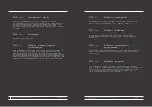
There is a possibility that an imbalance may exist
between the levels low/mid/high and left/right.
These imperfections can be set properly
by adjusting the level trim-pots. They can
atttenuate 2.5dB.
III.
6
Level
level
left balance
right balance


