40
© 2006, Elektro-Automatik GmbH & Co. KG
Irrtümer und Änderungen vorbehalten
EN
© 2006, Elektro-Automatik GmbH & Co. KG
About the power supply
3.4 Used symbols
In the following description the display and operating
elements are marked differently by symbols.
=
Displayed only
, all elements which are only
displayed and which represent a state are marked with this
symbol
=
Parameter
, changeable values, are marked with this
symbol and are emphasised
=
Menu items
, selectable, lead to the next sublevel or
to the bottom level with parameters
Brackets
{…}
mark possible options or adjustment ranges
for parameters.
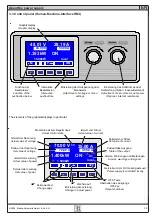
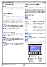
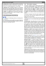
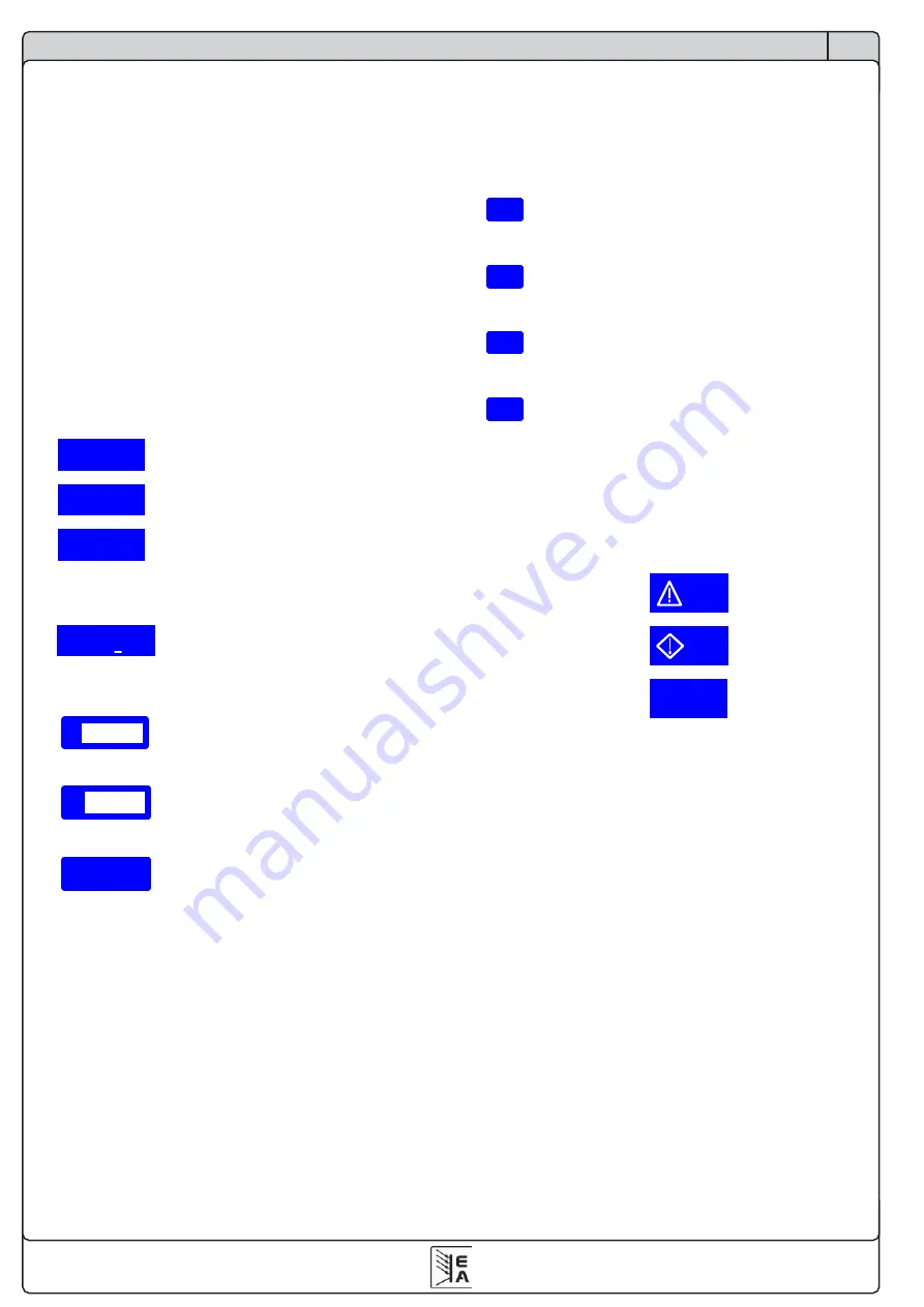
3.5Short overview about the display elements
70.00 V
Actual value of the output voltage
35.00 A
Actual value of the output current
1.400kW
Actual value of the output power
During normal operation the actual values are displayed in
big letters.
1.400kW
kW
>80%
Alternatively to the normal power value the
power derating mode is indicated. The total power is
automatically reduced in case of low mains voltage.
70.00 V
Set values of voltage
Target value of the desired output voltage (left knob).
40.50 A
Set value of current
Target value of the desired output current (right knob).
1500kW
Set value of the power
Target value of the desired maximum output power.
With the
SELECT
keys (see „6.3 Adjusting the set value“ for
details) you can switch the right knob to adjust the set value
of the power. The set value is then displayed invertedly and
you can change it.
The state of the power output is displayed in the bottom right
corner of the display.
{ON,OFF}
State of the power output
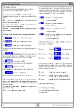
The currently active control mode is displayed to the right of
the related actual values. For instance, the abbreviation „CV“
is displayed next to the actual value of voltage, because it
means that „Control voltage“ mode is active. The output
values are limited by the active control mode:
CV
- limited by the voltage set value
(= Control Voltage)
CP
- limited by the power set values
(= Control Power)
CC
- limited by the set value of current
(= Control Current)
CR
- limited by the set value for internal resistance
(optional at U/I/R mode)
(= Control Resistance)
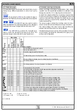
Additionally to the state of the output an alarm, a warning or
a signal can be displayed:
Alarm
Example:
OT
= Overtemperature
Warnings
Example:
U>
= Overvoltage
Signals
Example:
I>
= Overcurrent
The location from where the unit is currently controlled is
displayed below the output state. This location is absolute,
which means that you cannot control the unit from elsewhere
without changing the location.
local
Control only possible at the unit
remote
Remote control via communication
interfaces (IF-C1, IF-R1, IF-U1 etc.)
extern
Remote control via analogue interface
3.6 Scope of delivery
1 x Laboratory power supply
1 x Printed user instruction manual
1 x Mains cord

