44
© 2006, Elektro-Automatik GmbH & Co. KG
Irrtümer und Änderungen vorbehalten
EN
© 2006, Elektro-Automatik GmbH & Co. KG
Display
Alarm
Warning
Notification
with Auto ON
Signal
Description
OV
Overvoltage at the power output
SYS
General system error
FCT
Function layout could not be sent
1)
2)
1)
2)
3)
4)
3)
4)
CAN
Transmission error at CAN
SIO2
Communication of System Link Mode disturbed (System Link Mode)
U>
def. def.
def.
Overvoltage threshold reached
U<
def. def.
def.
Undervoltage threshold reached
I>
def. def.
def.
Overcurrent threshold reached
I<
def. def.
def.
Undercurrent threshold reached
U
def. def.
def.
Comparison error of actual/set value at a positive voltage step
U
def. def.
def.
Comparison error of actual/set value at a negative voltage step
I
def. def.
def.
Comparison error of actual/set value at a positive current step
I
def. def.
def.
Comparison error of actual/set value at a negative current step
P
def. def.
def.
Comparison error of actual/set value at a positive power step
P
def. def.
def.
Comparison error of actual/set value at a negative power step
S-P
One slave is reducing the maximum output power (System Link Mode)
S-?
One or multiple slaves are not connected to the master (System Link Mode)
M S
One or multiple slaves are offline (System Link Mode)
1)
Power On = OFF
2)
Power On = restore
3)
OT disappear = OFF
4)
OT disappear = auto ON
def. = definable
S-OT
Overtemperature of a slave (System Link Mode)
S-PH
Mains voltage or phase loss at a slave (System Link Mode)
OT
Overtemperature
Error type
Depending on
parameter
PH
Phase failure (only at multi-phase units)
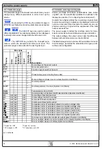
6.10 Alarms, warnings and signals
Alarms, warnings and simple noticifications (here called
„signals“) can be acoustically signallised or optically in the
display (see section „7.4 Configuring the control panel“).
An alarm has a higher priority than a warning or signal. Up to
four alarms, warnings or signals can be displayed, which will
cycle in an interval of three seconds. If an alarm occurs, one
previous warning or signal will be suppressed if the total
number exceeds four.
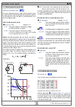
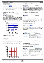
The power supply monitors the interface cards for trans-
mission errors as well user-defined warnings and alarms.
The output voltage, the output current and the difference
between actual and set value can be monitored.
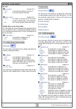
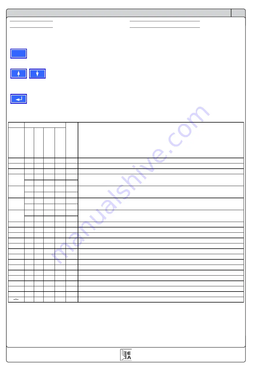
The table below gives an overview of the possible errors and
their meanings, as well as the selectable error types, as far
as these are configurable.
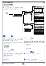
Using the power supply
6.9 Parameter pages
The parameter page is the lowest menu level. Here you can
change many different parameters in order to set up the
device.
ESC
By pressing the
ESC
key the parameter page is
left to the next higher level and no parameters are accepted.
The
SELECT
keys are used to select a
different parameter. The selected parameter is then displayed
invertedly and can be changed with the left rotary knob.
The
RETURN
key submits the changed para-
meters, which are accepted and stored and used. The
parameter page is also exited to the next higher level.

