background image

EDA-Z5008, Z5020 & Z5100 – User Manual  


 ZPControlUserMan_r100 

_____________________________________________________________________________________________________ 


10 


3.0 - Menu Operation 

 
To  enter  the  menu  system,  press 

Menu. 

This  will  display  an  overview  of  any  alarms,  faults, 

disablements  or  tests  that  are  currently  active,  along  with  an  option  to  access  the  Main  Menu.  The 
options available on the main menu and sub-menus will be dependent on the access code entered and 
its  corresponding  access  level.  To  scroll  through  the  menu  the 

  and 

  keys  should  be  pressed.  In 

order  to  select  a  menu option the 

  key  should  be  pressed.  To  return to the  previous  menu  screen 

from a sub-menu the 

← 

key should be pressed. Pressing 

Cancel

 will return to the system screen where 

any faults or alarms will be displayed if present.  
 
For every menu option listed in this manual, its place in the menu structure will be shown in grey text 
underneath  the  heading.  For  example,  the  event  log  can  be  found  by  selecting  the  ‘Main  Menu’, 
followed by ‘View Events’ and selecting ‘View Event Log’. 
 

1.Main Menu>>4.View Events>>2.View Event Log 

 
If a non-menu screen is selected the 

Cancel

 button should be pressed to return to the menu without 

making  any  changes.  Subsequently, then pressing 

Cancel

 for  a  second time  will  return  to the  system 

screen. If any changes are made to settings, these are generally saved using the 

Enter

 key as detailed 

on the display. If an alarm occurs while in menu mode, the menu will be automatically cancelled, and 
the alarm message displayed. If a fault occurs while in the menu mode, the fault LED will light but the 
display will remain in the menu mode until cancelled in the usual way.  
 

3.1 - Quick Menu – all access levels 

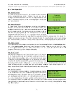
Pressing 

Menu 

once  will  display  the  Quick  Menu.  Navigate  using 

the cursor keys. Any active alarms, faults, disablements or tests will 
be  displayed.  No  access  code  is needed  to  view the  events  listed. 
You will only be prompted to enter an access code if you select 

‘1-

Main Menu’

 
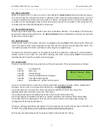
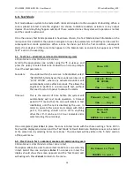
When  a  category  (e.g.  Faults)  is  selected,  the  first  screen  will 
display information such as the device number, zone, type of fault 
and any text location. 
 
 
Pressing  the  →  key  will  display  the  time  and  date  that  the  event 
happened. 


1>Main Menu 
2 Alarms(000) 
3 Faults(002) 
4 Disablements(000) 

001 Zn:001 SHORT CCT 
CONTROL IP1 

Time:12:00:08 
Date:25/06/13 

Summary of Contents for ZERIO PLUS EDA-Z5008

Page 1: ...ZERIO PLUS EDA Z5008 Z5020 Z5100 USER MANUAL ZPControlUserMan_r100 Revision 1 00 ...

Page 2: ...EN54 2 1997 A1 2006 EN54 4 1997 A1 2002 A2 2006 EN54 25 2008 Control and indicating equipment for fire detection and fire alarm systems for buildings Models EDA Z5008 EDA Z5020 EDA Z5100 Optional functions with requirements 7 8 Output to fire alarm devices 7 9 1 Output to fire alarm routing equipment 7 11 Delays to outputs 7 12 Dependency on more than one alarm signal Type C dependency 7 13 Alarm ...

Page 3: ... Z5020 Z5100 User Manual ZPControlUserMan_r100 _____________________________________________________________________________________________________ 3 Revision History V1 00 19 01 2015 User manual first release ...

Page 4: ... Part 25 Based on the popular Zerio system the updated Zerio Plus has been designed to be capable of handling 240 devices in 100 zones Typical installations would include small offices private houses HMO s guesthouses and small hotels This manual contains information to enable a user to operate the Zerio Plus control panel and the range of Zerio Plus devices This product should be installed commis...

Page 5: ... 0 User Operation 2 1 System Normal 2 2 Fault Conditions 2 3 Silence Buzzer 2 4 Reset a Fault 2 5 Alarm Conditions 2 6 Silence the Alarm 2 7 Re sound the Sounders 2 8 Reset the Alarm 2 9 Access Levels 3 0 Menu Operation 3 1 Quick Menu 4 0 Setup Menu 4 1 Time and Date 5 0 Disable Enable Menu 6 0 Test Mode 6 1 Test Zone 6 2 Clear Zone In Test 6 3 Lamp and Buzzer Test 7 0 Faults 8 0 Maintenance ...

Page 6: ...on exists across multiple zones multiple zone LEDs will be illuminated The zone LEDs will remain lit until the panel is reset The EDA Z5008 8 Zone panel is shown The EDA Z5020 panel is equipped with 20 zone LEDs and the EDA Z5100 is equipped with 100 zone LEDs Status LEDs Supply This LED will be illuminated when mains power is present Delays Active Illuminated if delays are enabled Disablements Il...

Page 7: ... a number of functions Cancel Used to return to the main screen from a menu or to return to the menu from a programming screen Enter This is used to accept information programmed into the panel Re sound Alarm Following an alarm condition that has been silenced but not reset this button will re sound the alarm Silence Alarm If the panel is in a fire condition this will silence the sounders Silence ...

Page 8: ...been pressed the panel assumes that the fault has been acknowledged and does not re sound the buzzer unless a new fault occurs The LED on the device will continue to flash until the fault is reset see below 2 4 Reset a Fault A fault will be displayed on the panel until the system is reset even if the fault condition has been rectified Assuming the fault has been rectified pressing Reset on the pan...

Page 9: ...alarm i e the glass has not been replaced in a callpoint or a smoke detector detects smoke is still inside the unit after silencing the alarm and pressing Reset the panel will redisplay the alarm and the sounders will sound again 2 9 Access Levels The panel is protected from misuse by means of four access levels The access levels are as follows Level 1 Untrained user Level 2A Basic user Level 2B A...

Page 10: ...in Menu 4 View Events 2 View Event Log If a non menu screen is selected the Cancel button should be pressed to return to the menu without making any changes Subsequently then pressing Cancel for a second time will return to the system screen If any changes are made to settings these are generally saved using the Enter key as detailed on the display If an alarm occurs while in menu mode the menu wi...

Page 11: ...d the LED marked Disablements will now be illuminated on the panel After the timeout period has elapsed the isolated zone s will automatically be re enabled Disable a Device all access levels 1 Main Menu 2 Disable Enable 1 Disable 2 Device If a device is disabled the system will not display any fire or fault events for that device Using the or keys select the device number to be disabled and press...

Page 12: ...ble LED will be illuminated After the timeout period has elapsed any disabled sounders will automatically be enabled again When sounders are disabled any hard wired sounder circuits will not display short circuit and open circuit faults Disable Fire Routing all access levels 1 Main Menu 2 Disable Enable 1 Disable 5 Fire Routing The fire routing relay can be disabled for a period of time specified ...

Page 13: ... have been enabled No Devices to enable will be displayed If a previously disabled device is enabled and no other isolated devices zones remain then the Disablements LED will extinguish Enable Panel Input all access levels 1 Main Menu 2 Disable Enable 2 Enable 3 Panel Input Select this option to enable an input that has previously been disabled Choose the input from the list and press Enter to con...

Page 14: ...ely the sounders can be set to 6 SEC SOUND where any activated sounders will automatically silence after 6 seconds This allows the engineer to perform a one man walk test without the need to return to panel to silence the alarm Timeout This is the amount of time before the system will automatically exit test mode operation A timeout period of 0 means that the zone will remain in test indefinitely ...

Page 15: ... based on BS5839 codes of practice Daily Actions The user should check that the panel indicates normal operation If any faults exist they should be recorded and the responsible person or maintenance company should be notified Weekly Actions The user should put at least one callpoint or detector in to alarm checking that the correct device zone is indicated on the panel and that the programmed soun...

Page 16: ...th LED Beacon 2 x EDA Q690 EDA T5000 Radio Transmitter Unit 1 x EDA Q690 EDA T5100 Radio Silence Alarm Button 1 x EDA Q690 EDA T6080 Radio Input Output Unit DC 1 x EDA Q690 EDA Y5000 Dipole Weatherproof Antenna EDA Z5008 8 Zone Radio Control Panel EDA Z5020 20 Zone Radio Control Panel EDA Z5100 100 Zone Radio Control Panel EDA Z6000 Radio Booster Panel with I O EDA Z6001 Radio Booster Panel EDA Z6...

Reviews: