12/20/2017
4
EI505
MECHANICAL
INSTALLATION
The heat pump manufacturer's starter collar should be centered over the discharge blower.
Generally the blower shaft is 9Ø
to the facing front of this Electro-Duct. In other words, if you
would be viewing the blower motor shaft, you would see the side of the electrical control box.
Also blower centering means, the approximate 3 inch opening of the blower discharge is
centered under the electric elements. It does not mean the complete blower housing discharge is
centered, only the actual blower discharge opening itself.
In the case of the Econar unit, the Electro-Duct right side extended lip (facing Electro-Duct
control box), simply lapse on the right side of the Econar cabinet and the Electro-Duct center
side hole alignment with Econar cabinet center side screw.
ELECTRICAL
HOOKUP
1. 240 VOLT SOURCE - Locate correct model number and KW size in Table 1 to determine
operating current and minimum source circuit breaker size. According to local codes,
building type, wiring run distance, etc., use the appropriate electric conductor size to
bring over the 240 volt source power. Connect to fuse block/input terminals (10KW is
terminal block only).
2. GROUNDING - Route and install the appropriate size ground conductor between the ground
lug labeled "GROUND" and building service entrance panel ground buss. This must be a
conductor sized according to the total amp rating of the appropriate model. Conduit is
not a adequate ground conductor.
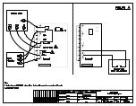
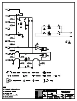
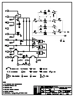
3. THERMOSTAT CONTROL - See drawing EH5Ø3 and previous Functional Description
section for basic hookup:
A. Outdoor stat is not required, factory jumper is provided between "W1" and "X".
B. "W2" is not available on 10KW models.
C. 10KW model can be operated from a two stage room stat ("W1" and "X"). Remove
jumper between "W1" and "X", connect stat "W1" to "W1" and "W2" to "X".

