background image

01/10/2008 6 

HI321 

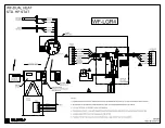
 WF-LGR4 & WF II WIRING & SETUP 


WF-LGR4 

Application

 – Standard heat pump room thermostat, heat pump, WF II Electro-Mate, gas/oil furnace.  HP 

manufacturer’s fossil fuel kit is 

not

 required. 


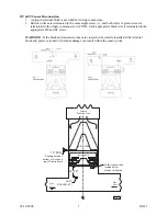
Reference Drawing HH340 


1.


The provided 10-wire cable includes all connections and functions between WF-LGR4 and the WF II 
main board within the Electro-Mate unit. 

a.


The 10-pin connector on the main WarmFlo II board originated manufacturing date 08-
04-04 (ARL 3074).  On the 10-pin connector may be a dummy cap plug, remove and 
expose all 10 pins. 

b.


If with this installation you do not have WarmFlo II main board with the 10-pin header, 
you can either update the WarmFlo board or call factory for special instructions for 
cutting up the cable and terminating with female ¼” tabs. 

c.


If this installation is with the new upgraded WarmFlo and the new WF+ control board, 
there is no thermostat, heat pump, furnace, load control wiring or field hookup on the 
WF+ board.  All thermostat, load control, etc. connections are on this separate enclosure 
board.  Even though the WF+ board is larger, when plugging in the 10-wire cable the 
WF+ board functions identical to the normal WarmFlo II main board. 

2.


All field connections and wiring from thermostat/heat pump/furnace are now are directly at this 
controller, there are no bypass wires. 

3.


Room Thermostat Connections

 – upper left terminal block, 5 or 6-wire cable. 

a.


Terminology is universal, should match most any heat pump room thermostat. 

b.


The W at the roomstat is 

not used

c.


Since this controller is single speed only, there should only be a Y1. 

d.


Do not use

 “dual fuel” or complex/sophisticated room thermostat. 

e.


If you desire to use the roomstat emergency lever or function, you have a choice to 
connect the “E” screw to either WF or GAS tab.  Electro recommends WF (full plenum 
heater output) and use the override switch in the front of this controller as your gas 
switchover. 

4.


Heat pump outdoor unit

 – upper right terminal block, 4 or 5-wire cable.  Terminology should be 

universal, but some units provide colored wires only.  Installer will need to match the wire color to 
these lettered functions. 

R – 24-volt power 
C – 24-volt common 
Y – compressor contactor coil 
RV (O) – reversing valve, typically orange 

a.


As an option (if the installer is absolutely confident of this function), the defrost output 
wire can be connected to DF (W1) tab to increase the plenum heater kW output (all 
stages on immediate) when the outdoor unit initiates defrost. 

b.


Since this controller can only be used for single speed equipment, there should only be a 
single Y function. 

c.


These are the only connections or wires needed from the outdoor unit. 

5.


Furnace terminal block

 – bottom center terminal block, 4 or 5-wire cable.  Terminology should be 

universal. 

a.


The Y is only needed for variable speed, ECM motor, type blowers. 

b.


The power for this controller and the Electro-Mate/WarmFlo comes from the furnace 
transformer and is R and C at this bottom terminal block. 

6.


Utility Load Control

 – if utility load control applies, remove the blue jumper from the bottom left 

terminal block and connect the utility NC contact receiver or device. 

a.


If opposite control logic is required, contact factory for other wiring instructions. 


Summary of Contents for WARMFLO II

Page 1: ...ss through Improved stat emergency heat function no longer requiring extra relay Reversing valve detection relay positive WarmFlo and gas furnace interrupt during cooling RV logic pin jumper setup required Front panel cool light Equipped for ECM blower motor direct Y connection Faster defrost response Easier single cable plug in to the upgraded 10 pin connector WarmFlo II board Reference Field Ser...

Page 2: ...High Voltage 4 Low Voltage 4 Outdoor Sensor OT 4 Supply Sensor ST 4 WF LGR4 WF II Wiring Setup 6 Chip Code HPDH 8 HPDF 9 HPEL 10 OPERATION INDICATORS 12 Furnace Interface Module 12 WarmFlo II Controller 12 HANDHELD ANALYZER LAPTOP SOFTWARE 14 SPECIAL APPLICATION INSTALLATION 15 For Various Heat Pump Multi Speed Multi Stage Furnaces Blower Options Oil Furnace etc OPTIONAL ACCESSORIES 16 TROUBLESHOO...

Page 3: ...or etc If one of these components is missing or not initially installed improper performance of WarmFlo II and the system may be experienced In other words if the gas furnace doesn t exist LP tank not yet installed or filled and the WarmFlo II is operating on a cold day do not be disappointed if there is no heat Warranty Checkout Attached to this manual is a warranty certification and checkout pro...

Page 4: ...e hi limit probe the WarmFlo II supply sensor basically gets confused because at one point it is way up in temperature and then the elements simply disappear and it dips down the net result probably is switching over to standby at premature intervals There is no substitute for adequate airflow capacity and plenum baffling EM WD Electro Mate Horizontal Application NOTE It is not permissible to rota...

Page 5: ...do not have the required CFM airflow example 20 kW 1400 CFM you could have a situation where you cannot heat the house Another even more serious situation because of improper airflow is when all stages are on at colder temperatures and the unit is cycling on mechanical safety hi limit When cycling on the hi limit probe the WarmFlo II supply sensor basically gets confused because at one point it is...

Page 6: ...pacitance prefer twisted 3 or 4 wire low voltage cable 35 foot maximum b Do not under any circumstances use leftover wires within the thermostat cable going to the outdoor unit 4 Mount OT sensor with sensor tip up cable downward 5 Drill hole near the outside sensor location Routing the cable along the freon tubing often makes the easiest installation 6 Route wire from outside making sure not to cr...

Page 7: ...black wire is terminated in the appropriate OT and ST screw WARNING If the black and red sensor wires are crossed or incorrectly installed at the terminal block and power is turned on burnout damage can result within the sensor probe ELECTRO MATE Dist Duct Dist Duct Furnace Downflow Only EI708 03 Rev C 04 27 04 DUCT SENSOR ST Hi limit sensor tube located below element in heated 14 18 1 0 MIN Spaci...

Page 8: ...c Since this controller is single speed only there should only be a Y1 d Do not use dual fuel or complex sophisticated room thermostat e If you desire to use the roomstat emergency lever or function you have a choice to connect the E screw to either WF or GAS tab Electro recommends WF full plenum heater output and use the override switch in the front of this controller as your gas switchover 4 Hea...

Page 9: ...L represents when the reversing valve is high or at 24 volts Example pin jumper between center and COOL means the reversing valve wire is at 24 volts during cooling The factory default is pin jumper setup for cool high Important if there is operational difficulty during defrost with the reversing valve O wire changing states during defrost or a RV logic high during heating application using stat B...

Page 10: ...p and Electro Mate stages again attempt to produce the WarmFlo II desired temperature Again if everything is at 100 plus the MU time the gas furnace takes over HPDH Chip Code Electro Mate Sized for Complete Heating Load Application 8 wire standard heat pump thermostat WF II Electro Mate Heat Pump gas oil furnace using ODT to control heat pump only The WarmFlo II controller with this chip has outsi...

Page 11: ...ithin WarmFlo and within Electro s various heating products to add partial resistance heating section to heat pumps To provide optimum operation and comfort the setup functions need to be activated accordingly Default program code chip HPDF has been designed for this application As a field setup you probably want MU to be relatively short 30 minutes the ODT mode will be EL to SB with a dial switch...

Page 12: ...il furnace This code will only allow gas oil on during utility control The WarmFlo II controller with this chip has outside temperature reference for enabling the electric heat staging except E tab The outside temperature actual sensor must be below these values before the stage will come on independent of supply sensor requirement Stage 1 5Ø F 2 38 F 3 36 F 4 34 F MU Time disabled or 00 WF II DIA...

Page 13: ...ull the WF II will automatically go to DT flat WF LGR4 adjustments and settings The normal standby switch provides the standard user override function some power companies request inactivation or deletion of this switch Requires selection of the proper RV logic at the LGR4 board top center see previous page Reference WarmFlo Handheld Analyzer Laptop Software section in this manual for changes to y...

Page 14: ...n can also be on a remote switch see page 16 SB tab Blower Operation the blower function is totally within this controller and has nothing to do with the main WarmFlo board The stat G function is directly channeled to the furnace G The thermostat Y and E activate an internal furnace G with an approximate 10 second turn on delay and a 1 minute turn off delay The furnace Y is also activated when the...

Page 15: ...ondition red LED is illuminated As soon as the hi limit cools and snaps back in red LED extinguishes Triac Relay Module under inside relay board This module has its own built in LED When the LED is on the triac switch is closed elements will be heating This LED shall operate coincident with Stage 1 on the WarmFlo board COMMENT The relay board activates from the WarmFlo II main board as WarmFlo II ...

Page 16: ...p to all stages full on DT flat in order to more rapidly raise the building temperature However this also means you will be short cycling the HP compressor during other heat calls The maximum run time for the compressor is then about 30 minutes at any time of the day or at any particular heat call Notice Effective program code chips after 7 7 04 the SOT S has been factory set at 90 minutes This is...

Page 17: ...od furnace so that the discharge temperature does not exceed 180 F 2 Stage Gas Furnace from Electro s experience all 2 stage gas furnaces must have a W1 before reacting to a W2 or special variable burner second control wire Realizing this any of these W2 functions from a special roomstat can go directly to the furnace terminal block This LGR4 properly handles W1 which is the main control function ...

Page 18: ...circuit appliance electric heater TROUBLESHOOTING Comment Also see the WarmFlo Information document HD320 included with this manual Sensor Temperature Calibration Both remote sensors are digital electronic and factory calibrated Normally these do not require field calibration or verification However if sensor temperature error is determined there are two field calibration techniques Proceed with e...

Page 19: ...temperature offsets for assimilating winter conditions and reprogram the control chip program stays with the actual controller board Bad sensor safety if the internal logic detects open sensor wire incorrectly wired sensor or some bad sensor transmitted value conditions the green LED reverts to a pulsing mode Basically the appropriate sensor is set internally to a 0 value and the WarmFlo main boar...

Page 20: ...O CONTROLLER SEE DETAIL A WF LGR4 Furnace Gas Oil R G C W GREEN G BLUE C RED R WHITE W FAN CENTER OUTDOOR UNIT DEFROST Y W1 R O C YELLOW ORANGE RED BLUE T7 T9 T8 BLUE BLUE WHT R G Y O C E WF E GAS HP STAT HEAT COOL RV LOGIC HI R Y RV O C DF W1 HP UNIT SB R W G C Y C C R FURNACE UPCB6708 CS T1 T2 T3 K2 K5 K3 K1 K4 T6 F1 T10 TB2 TB1 T5 T4 L E D 3 L E D 2 L E D 5 L E D 4 L E D 1 S W 1 TB3 TB4 J1 J2 B...

Page 21: ...o immediately jump up to this highest value However on consecutive thermostat calls it will immediately step to the DT Flat temperature value Note This is essentially the same as DT Flat and again all four stages do not automatically go to full on Staging Disable Temperature in all OT active sensor applications DT cal there is a setup program temperature to hold off each stage for warmer heating c...

Page 22: ...rature However this also means you will be short cycling the HP compressor during other heat calls The maximum run time for the compressor is then about 30 minutes at any time of the day or at any particular heat call Note Beginning approximately 7 04 the SOT S has been factory default at 90 minutes for all dual heat chip codes MU this is an internal timeout function which begins when all stages a...

Page 23: ... at each heat call If after the 5 minutes the ST sensor is less than 80 the logic board itself goes into an automatic reset and restart This simply means it attempts to begin the heat cycle using electric in case the furnace did not ignite or out of gas However if it is in the SB mode because of Load Control it will still remain SB and try the gas furnace again The system will never go back to ele...

Page 24: ...tab with HP stat emergency output see previous E tab section for blower operation caution Bad sensor safety if the internal logic detects open sensor wire incorrectly wired sensor or some bad sensor transmitted value conditions the green LED reverts to a pulsing mode Basically the appropriate sensor is set internally to a default value and there will be an attempt to cause the electric heat output...

Page 25: ...s It is smart enough to know it is no longer the original chip and that specific physical board from this time forward must be under the control of the PC software Handheld However a new totally different coded chip with the same or different revision date will automatically wipe out any of the previous setups and can restart the same physical board based on the defaults within this newly added or...

Page 26: ...system can only deliver greater than 100 if it s running let it run Because of WarmFlo s design concept and its internal brain the heat loss curve diagonal lines below allows the compressor to operate with a minimal amount of electric resistance supplement or temperature boost Heat loss curve within the brain of the WarmFlo controller is a relationship of supply temperature ST to outdoor temperatu...

Page 27: ...g the higher the overall operating annual efficiency the higher the setting the warmer the air at the register Chip code field programming your unit was ordered and supplied with a coded program chip one of the selections shown in each Chip Code Reference Table for your application within the various colored page sections These tables show the various defaults associated with that particular code ...

Page 28: ......

Page 29: ...ade by Electro Industries or its authorized representative Electro Industries will cover reasonable labor costs to repair defective product or product parts for ninety 90 days after installation TWENTY YEAR 20 LIMITED WARRANTY ON BOILER ELEMENTS AND VESSELS Electro Industries Inc warrants that the boiler elements and vessels of its products are free from defects in materials and workmanship throug...

Page 30: ...ill be null and void 4 The purchaser shall have maintained the product in accordance with the manual that accompanies the unit Annually a qualified and licensed contractor must inspect the product to assure it is in proper working condition 5 All related heating components must be maintained in good operating condition 6 All lines must be checked to confirm that all condensation drains properly fr...

Reviews: