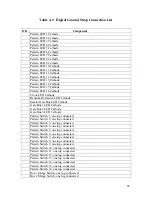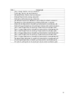
Digital Ground Strap Connection Procedure
o
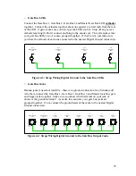
Pattern LEDs 1 through 16
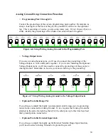
Connect all of the pattern LED
cathodes
together. By now, you’ve probably got a
pretty good idea which lead is the cathode. If not, go back and read the first sections
of this document again. Connect the cathodes together about one quarter to a half
inch from the rear of the LED. Don’t let that LED get too hot! Snip off any excess
cathode lead length. Don’t connect anything to the anodes yet. That all comes later.
Anode
Cathode
D16
Stage 1
Red LED
Anode
Cathode
D15
Stage 15
Red LED
Anode
Cathode
D14
Stage 14
Red LED
Anode
Cathode
D13
Stage 13
Red LED
Anode
Cathode
D12
Stage 12
Red LED
Anode
Cathode
D11
Stage 11
Red LED
Anode
Cathode
D10
Stage 10
Red LED
Anode
Cathode
D9
Stage 9
Red LED
Anode
Cathode
D8
Stage 8
Red LED
Anode
Cathode
D7
Stage 7
Red LED
Anode
Cathode
D6
Stage 6
Red LED
Anode
Cathode
D5
Stage 5
Red LED
Anode
Cathode
D4
Stage 4
Red LED
Anode
Cathode
D3
Stage 3
Red LED
Anode
Cathode
D2
Stage 2
Red LED
Anode
Cathode
D1
Stage 1
Red LED
Figure 4-1: Strap Wiring Digital Ground to the Pattern LEDs
o
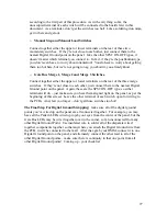
Pattern Switches 1 through 16.
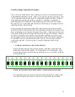
Connect all of either the upper or lower terminals on the rear of the pattern switches
together. By now, you’ve already oriented them so they point to the right label on the
front panel. Now, it doesn’t matter if you connect the common ground to either the
upper or lower terminal at the rear of the switch. Since they’re all in a line (unless
you have some cool circular panel going on), it’s easier to connect all the terminals
together in a line. Each switch will have only one of its terminals connected – don’t
get all crazy and solder both terminals of each switch to something yet. The
unoccupied terminal of each switch will be connected to the boards later in this
procedure. Be careful when soldering your switches –
don’t get them too hot
.
You’ll know you did if the lug starts to “swim around” in its plastic potting material.
As you string the wire along from lug to lug, give the switch time to cool off before
you attach the wire from it to the next lug down the line. These switches are, if not
the lifeblood of the Klee, surely its spinal fluid.
SW1
Stage 1
SPST ON-OFF
SW2
Stage 2
SPST ON-OFF
SW3
Stage 3
SPST ON-OFF
SW4
Stage 4
SPST ON-OFF
SW5
Stage 5
SPST ON-OFF
SW6
Stage 6
SPST ON-OFF
SW7
Stage 7
SPST ON-OFF
SW8
Stage 8
SPST ON-OFF
SW9
Stage 9
SPST ON-OFF
SW10
Stage 10
SPST ON-OFF
SW11
Stage 11
SPST ON-OFF
SW12
Stage 12
SPST ON-OFF
SW13
Stage 13
SPST ON-OFF
SW14
Stage 14
SPST ON-OFF
SW15
Stage 15
SPST ON-OFF
SW16
Stage 16
SPST ON-OFF
Figure 4-2: Strap Wiring Digital Ground to the Pattern Switches
24


