Back
of
Pot
Back
of
Pot
Back
of
Pot
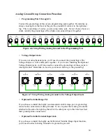
R20
Glide A
1M Linear
R19
Glide A+B
1M Linear
R21
Glide B
1M Linear
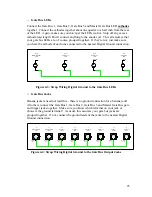
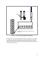
Figure 4-12: Wiring the Unused Lug to the Center Tap of the Glide Pots
From this point on, the steps listed are for optional installments only. They’re optional
mainly because the “standard” issue of the Klee was set in stone before the groovy
functions of these options were fully appreciated. Otherwise, they would have been part
of the standard package, along with the undercoating and whitewall tires.
o
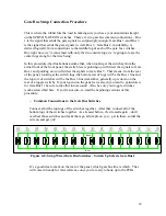
External Load Signal Input Jack to Optional External Load Enable Switch
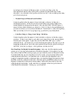
If you have decided to put in the optional External Load Enable Switch, connect a
wire from the “tip” lug of your External Load Signal Input Jack to the External Load
Enable Switch. It’s an SPST ON-OFF switch, so for now, you can connect it to either
terminal of the switch. If you didn’t put in the optional switch, drill a hole and put
one in – you’ll find it’s pretty handy. Or not.
This option appears on page 6 of the front panel/interconnect schematic.
J12
External Load
Input
Ground
Lug
Tip
Lug
SW345
Ext. Load
Enable
SPST ON-OFF
Figure 4-13: Connecting External Load Input Jack to Optional Load Enable Switch
The final optional common connections cover the ways the optional Variable Range
Control can be implemented. There are actually four configurations. The first option, a
single control that supplies a variable range, was covered in the Analog Ground Strap
wiring section. That option does not require any additional strap wiring. The remaining
three options involve injecting an external signal into the Klee, and using that signal as
the maximum range of the programming pots. Remarkably enough, that is called the
36


