1
2
3
4
5
6
7
8
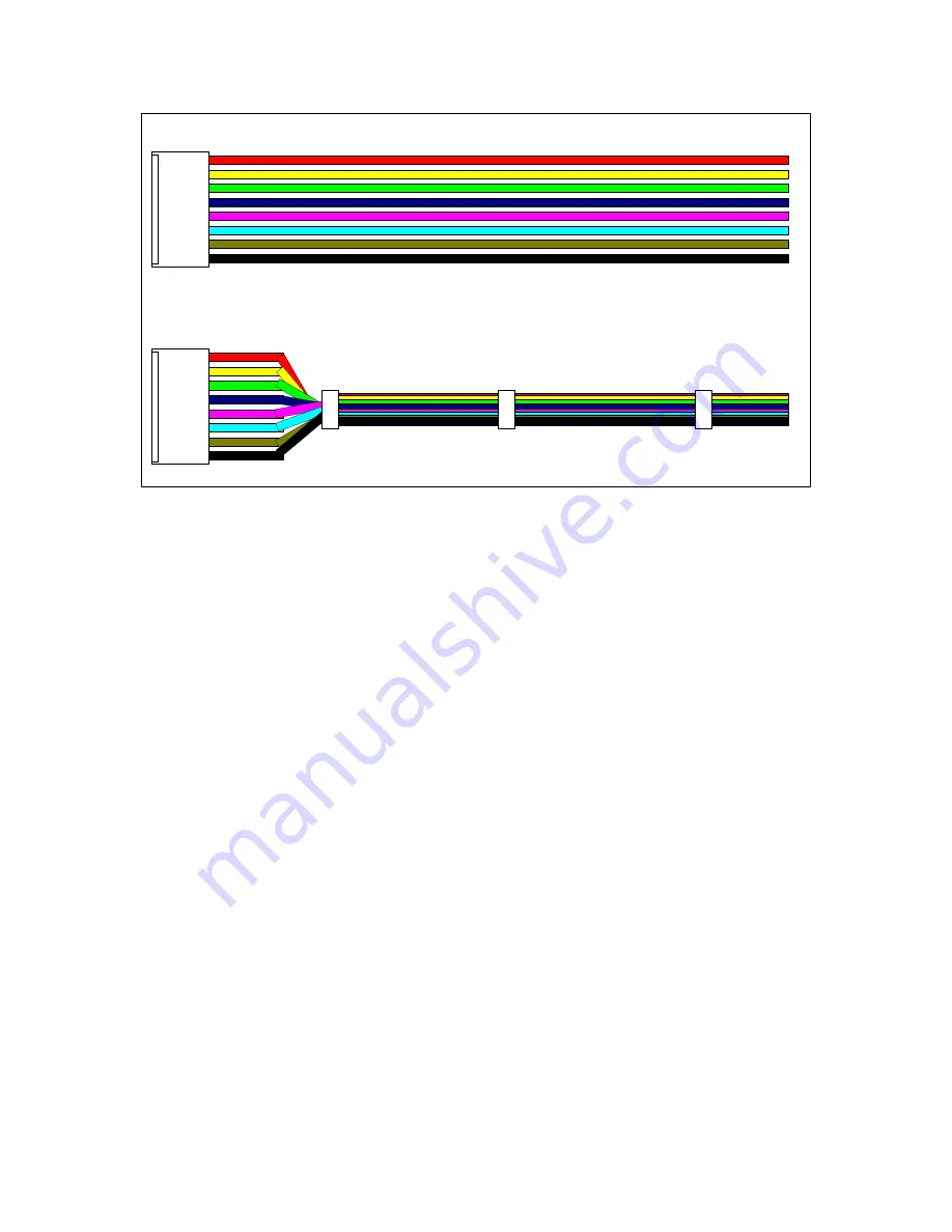
Figure 5-5: Assembled Cables
Once you’ve got all the wires into the housing, you can put a small collar onto the wires
just above the housing. You may not want to add more at this time, because your wires
will need to “fan out” in order to connect the all the disparate points they will connect to.
Once you’ve built your cables, you will find that soldering them to your strap-wired
panel is a real cinch – very easy, and all the real work will be behind you.
Sooo……what cables need to be built and how many of them?
Following are a set of cable-tables (how cool is that?). The tables describe how many 8
wire cables need to be built, how many 6 wire cables, and so on. The tables also provide
information as to which pin must be connected to what on the panel. The cables are
named by the number the housing is assigned to – a “P” followed by a designation. The
“P” means “plug”, and the designation does have some useful information built into it as
well.
The designation numbers come in two flavors – they either start with a 1 (such as P103)
or they start with a 2 (such as P204).
Those designators that start with a 1 are “100 Series” designators. All of the 100 series
designators will plug into the Digital Board. The number that follows the series
designator is actually the board’s designator as to which connector the plug will connect
to. For example, P103 will plug into J3 of the Digital Board. P107 will plug into J7 of
the Digital Board.
The 200 series designators will all plug into the Analogue Board. P204 will plug into J4
of the Analogue Board; P212 will plug into J12 of the Analogue Board and so on.
45


