background image

Safety

Suspension

!

Warning!
Suspending any object is potentially dangerous and should only be attempted by individuals
who have a thorough knowledge of the techniques and regulations of suspending objects
overhead. Electro-Voice strongly recommends all loudspeakers be suspended taking into
account all current national, federal, state, and local laws and regulations. It is the
responsibility of the installer to ensure all loudspeakers are safely installed in accordance
with all such requirements. When loudspeakers are suspended, Electro-Voice strongly
recommends the system be inspected at least once per year or as laws and regulations
require. If any sign of weakness or damage is detected, remedial action should be taken
immediately. The user is responsible for making sure the wall, ceiling, or structure is capable
of supporting all objects suspended overhead. Any hardware used to suspend a loudspeaker
not associated with Electro-Voice is the responsibility of others.

Safety point
As an added safety measure, it is suggested the user install an extra suspension point back to
the building structural supports. This safety point should have as little slack as possible (less
than 1-inch is preferable).

Notices

Old electrical and electronic appliances
Electrical or electronic devices that are no longer serviceable must be collected separately and
sent for environmentally compatible recycling (in accordance with the European Waste
Electrical and Electronic Equipment Directive).
To dispose of old electrical or electronic devices, you should use the return and collection
systems put in place in the country concerned.
Copyright and disclaimer
All rights reserved. No part of this document may be reproduced or transmitted in any form by
any means, electronic, mechanical, photocopying, recording, or otherwise, without the prior
written permission of the publisher. For information on getting permission for reprints and
excerpts, contact Electro-Voice.
The content and illustrations are subject to change without prior notice.

1

1.1


1.2

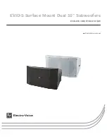
EVID-S Surface Mount Dual 10” Subwoofers


2017.08 | 01 | F.01U.345.359

Installation manual

Electro-Voice

Summary of Contents for EVID-S10.1DB

Page 1: ...EVID S Surface Mount Dual 10 Subwoofers EVID S10 1DB EVID S10 1DW en Installation manual...

Page 2: ......

Page 3: ...onal accessory 12 4 6 Installing the crossover input panel optional accessory 14 5 Wiring 15 5 1 Standard input panel 15 5 1 1 Mono operation 15 5 1 2 Stereo operation 16 5 2 Transformer input panel o...

Page 4: ...others Safety point As an added safety measure it is suggested the user install an extra suspension point back to the building structural supports This safety point should have as little slack as pos...

Page 5: ...oofer 2x10 black EVID S10 1DW Cabinet subwoofer 2x10 white UB 10DB U bracket for 10 subwoofer black UB 10DW U bracket for 10 subwoofer white IP 10D TB Transformer input 10 subwoofer bk IP 10D TW Trans...

Page 6: ...engineered to resist outdoor environments without compromising on performance for indoor applications The subwoofer is IP54 rated and its weather proofing is complemented with exceptional cabinet and...

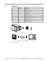
Page 7: ...n wrench E 1 Weather input cover F 8 Screws for weather input cover G 2 IP65 port covers H 12 IP65 port cover screws I 1 Installation manual Table 3 1 Components list A x 1 C I E F x 8 G x 2 H x 12 D...

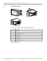
Page 8: ...own upside down Item Description A Grille B U bracket mounting points C M8 flying points D M8 safety point E Input panel F Subwoofer feet G Weather input cover Table 3 2 Product information 3 3 EVID S...

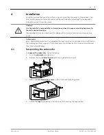
Page 9: ...njuries may occur Safety point As an added safety measure it is suggested the user install an extra suspension point back to the building structural supports This safety point should have as little sl...

Page 10: ...able 8 Secure the subwoofer from the safety eyebolt using rated fittings and steel cable See also Replacing the logo page 10 Replacing the logo An additional logo is included vertical installation is...

Page 11: ...ecurely tighten the screws for the IP65 port cover to prevent water leaks If the IP65 port cover is not properly installed you may cause damage to the subwoofer 1 Remove the grille 2 Install the IP65...

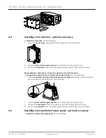
Page 12: ...n fire position do the following 1 Install two 8 mm rated forged eyebolts using lock washers eyebolts and lock washers not included into the fly points on the U bracket 2 Install an 8 mm rated forged...

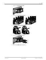
Page 13: ...panel 2 Disconnect the standard input panel 3 Connect the transformer input panel 4 Install the transformer input panel 5 Install the weather cover if applicable en 13 Electro Voice Installation manu...

Page 14: ...following 1 Remove the standard input panel 2 Disconnect the standard input panel 3 Connect the crossover input panel 4 Install the crossover input panel 5 Install the weather cover if applicable 4 6...

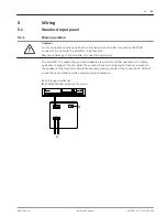
Page 15: ...ifier the subwoofer and the speakers are wired for MONO operation It is highly advisable to support the unit while these connections are being made Connect all wires to the speaker at the back termina...

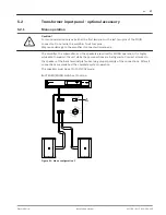
Page 16: ...s are being made Connect all wires to the speaker at the back terminal plate observing proper polarity of the connections After all connections are made test the complete system operation A Full range...

Page 17: ...ofer and the speakers are wired for MONO operation It is highly advisable to support the unit while these connections are being made Connect all wires to the speaker at the back terminal plate observi...

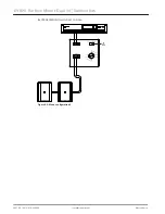
Page 18: ...A STEREO MONO switch set to mono A Figure 5 2 Mono configuration 2 EVID S Surface Mount Dual 10 Subwoofers 2017 08 01 F 01U 345 359 Installation manual Electro Voice...

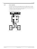
Page 19: ...connections are being made Connect all wires to the speaker at the back terminal plate observing proper polarity of the connections After all connections are made test the complete system operation Th...

Page 20: ...re wired for MONO operation It is highly advisable to support the unit while these connections are being made Connect all wires to the speaker at the back terminal plate observing proper polarity of t...

Page 21: ...ires to the speaker at the back terminal plate observing proper polarity of the connections After all connections are made test the complete system operation Both options shown are using 8 ohm speaker...

Page 22: ...O MONO switch set to stereo B HI PASS 4 OHM 8 OHM switch set to 4 ohm A B Figure 5 4 Stereo configuration 2 EVID S Surface Mount Dual 10 Subwoofers 2017 08 01 F 01U 345 359 Installation manual Electro...

Page 23: ...peakers are connected out of polarity out of phase the low frequencies will cancel each other acoustically Carefully observe the wire markings or tracers on your speaker wires Verify the amplifier ter...

Page 24: ...lock Input and output Max wire size 12 AWG 2 5 mm Environmental IP 54 per IEC 60529 IP 65 with port covers Color Black RAL 9004 or white RAL 9003 Dimensions H x W x D 356 mm x 651 mm x 491 mm 14 0 in...

Page 25: ...in 356 0 mm 14 02 in 360 5 mm 14 19 in 578 8 mm 22 79 in 650 7 mm 25 62 in 532 3 mm 20 96 in Frequency response and impedance Figure 7 1 Frequency response and impedance 7 1 7 2 en 25 Electro Voice I...

Page 26: ...Figure 7 2 Frequency response and impedance with cross over EVID S Surface Mount Dual 10 Subwoofers 2017 08 01 F 01U 345 359 Installation manual Electro Voice...

Page 27: ...39 in 8x 38 1 mm 8x 1 50 in 2x 21 0 mm 2x 0 82 in 2x 21 0 mm 2x 0 82 in 4x 22 5 mm 4x 0 87 in 4x 22 5 mm 4x 0 89 in 3x 13 0 mm 3x 0 51 in 632 0 mm 24 88 in 220 0 mm 8 66 in 220 0 mm 8 66 in 2x 21 0 m...

Page 28: ...tssysteme GmbH Robert Bosch Ring 5 85630 Grasbrunn Germany www boschsecurity com Bosch Sicherheitssysteme GmbH 2017 Bosch Security Systems Inc 12000 Portland Avenue South Burnsville MN 55337 USA www e...

Reviews: