background image

Safety

Old electrical and electronic appliances
Electrical or electronic devices that are no longer serviceable must be collected separately and
sent for environmentally compatible recycling (in accordance with the European Waste
Electrical and Electronic Equipment Directive).
To dispose of old electrical or electronic devices, you should use the return and collection
systems put in place in the country concerned.

Suspension

!

Warning!
Suspending any object is potentially dangerous and should only be attempted by individuals
who have a thorough knowledge of the techniques and regulations of suspending objects
overhead. Electro-Voice strongly recommends all loudspeakers be suspended taking into
account all current national, federal, state, and local laws and regulations. It is the
responsibility of the installer to ensure all loudspeakers are safely installed in accordance
with all such requirements. When loudspeakers are suspended, Electro-Voice strongly
recommends the system be inspected at least once per year or as laws and regulations
require. If any sign of weakness or damage is detected, remedial action should be taken
immediately. The user is responsible for making sure the wall, ceiling, or structure is capable
of supporting all objects suspended overhead. Any hardware used to suspend a loudspeaker
not associated with Electro-Voice is the responsibility of others.

Redundant safety point
As an added safety measure, it is suggested the user install an extra suspension point back to
the building structural supports. This redundant safety point should have as little slack as
possible (less than 1-inch is preferable).

Notices

Copyright and disclaimer
All rights reserved. No part of this document may be reproduced or transmitted in any form by
any means, electronic, mechanical, photocopying, recording, or otherwise, without the prior
written permission of the publisher. For information on getting permission for reprints and
excerpts, contact Electro-Voice.
The content and illustrations are subject to change without prior notice.

1

1.1


1.2

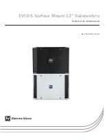
EVID-S Surface Mount 12” Subwoofers


2017.08 | 01 | F.01U.347.028

Installation manual

Electro-Voice

Summary of Contents for EVID-S12.1B

Page 1: ...EVID S Surface Mount 12 Subwoofers EVID S12 1B EVID S12 1W en Installation manual ...

Page 2: ......

Page 3: ...stem features 5 2 2 Product information 5 2 3 Packing list 6 3 Installation 7 4 Wiring 9 5 Troubleshooting 10 6 Technical data 11 6 1 Dimensions 11 6 2 Frequency response and impedance 12 7 Appendix A painting process 13 en 3 Electro Voice Installation manual 2017 08 01 F 01U 347 028 ...

Page 4: ...the system be inspected at least once per year or as laws and regulations require If any sign of weakness or damage is detected remedial action should be taken immediately The user is responsible for making sure the wall ceiling or structure is capable of supporting all objects suspended overhead Any hardware used to suspend a loudspeaker not associated with Electro Voice is the responsibility of ...

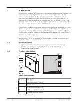
Page 5: ... wall corner or on a wall ceiling mid wall junction The included forged steel eyebolt provides the installer a solid attachment point for a safety line The EVID S12 1 subwoofer may also be safely installed protruding just 2 3 4 down through a standard suspended ceiling grid Read through this manual to familiarize yourself with the safety information features and applications before you use these p...

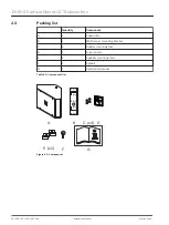
Page 6: ...cket C 4 Rubber mounting feet D 1 Logo spare E 2 Speaker mounting clips F 1 Eyebolt G 1 Installation manual Table 2 2 Components list A C x 4 G F E x 2 B D Figure 2 2 Components 2 3 EVID S Surface Mount 12 Subwoofers 2017 08 01 F 01U 347 028 Installation manual Electro Voice ...

Page 7: ...orner leave 1 5 inches 40 mm between the bracket and the ceiling Use a minimum of four screws Stud Wall Bracket Wall Stud 2 Wire the speaker as shown in the wiring section 3 Remove the two Philip head screws on the rear of the subwoofer 4 Mount one mounting clip to the top of the speaker using the eyebolt supplied 5 Attach the four rubber feet inside the corners on the side of the enclosure that w...

Page 8: ...eaker as shown in the wiring section 3 Remove the two Philip head screws on the rear of the subwoofer 4 Mount one mounting clip to the top of the speaker using the eyebolt supplied 5 Attach the four rubber feet to the front side edges 6 Lift the enclosure and center it back into the corner until it touches the bracket rungs 7 Carefully lower the enclosure so the top mounting clip hooks over the to...

Page 9: ...peaker at the back terminal plate observing proper polarity of the connections After all connections are made test the complete system operation L L R R from amplifier to speakers Left 1 Right 1 Right 2 Left 2 Figure 4 1 Direct wiring plan L L R R from amplifier Left 1 Right 1 Right 2 Left 2 Figure 4 2 Daisy Chain wiring plan 4 en 9 Electro Voice Installation manual 2017 08 01 F 01U 347 028 ...

Page 10: ...nnected out of polarity out of phase the low frequencies will cancel each other acoustically Carefully observe the wire markings or tracers on your speaker wires Verify the amplifier terminal is connected to the red speaker terminals and the amplifier terminal is connected to the black speaker terminals Improperly Wired Subwoofer Panel Using a test speaker as described above verify all amplifier a...

Page 11: ...004 or white RAL 9003 Dimensions H x W x D 413 mm x 584 mm x 303 mm 16 3 in x 23 0 in x 11 9 in 3 Net weight 17 8 kg 39 2 lb 3 Shipping weight pair 22 4 kg 49 4 lb Included hardware 1 Wall mounting hardware Packaged quantity 1 1 Eighth 1 8 space corner mounting 2 Eighth 1 8 space on corner averaged 60 Hz 100 Hz 1 W 3 Without mounting hardware Dimensions 584 2 mm 23 00 in 412 8 mm 16 25 in 303 3 mm...

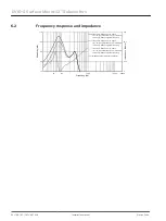
Page 12: ...1 2 watt per voice coil without signal processing Frequency Response 1 4 space 1W 1m both inputs driven 1 2 watt per voice coil without signal processing Frequency Response 1 2 space 1W 1m both inputs driven 1 2 watt per voice coil without signal processing Impedance both inputs in parallel 6 2 EVID S Surface Mount 12 Subwoofers 2017 08 01 F 01U 347 028 Installation manual Electro Voice ...

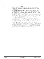
Page 13: ...rsh detergents or other chemicals as these agents may cause permanent damage to the enclosure After cleaning apply two or more two thin coats of either latex or oil based paint Spraying is recommended but a brush and small roller work very well It is not necessary to paint all the way up to the woofer Only the visible surfaces need to be painted the hatch front and side edges the exposed enclosure...

Page 14: ......

Page 15: ......
Page 16: ...itssysteme GmbH Robert Bosch Ring 5 85630 Grasbrunn Germany www boschsecurity com Bosch Sicherheitssysteme GmbH 2017 Bosch Security Systems Inc 12000 Portland Avenue South Burnsville MN 55337 USA www electrovoice com ...

Reviews: