MH6040AC Coaxial Constant-Directivity Manifold Technology
Horn System
8
MH6040AC Coaxial Constant-Directivity Manifold T
echnolog
y
Horn System
HORNS
Part Number 535623 — 9927
600 Cecil Street, Buchanan, MI 49107
616/695-6831, 616/695-1304 Fax
©Telex Communications, Inc., 1999 • Litho in U.S.A.
Specifications:
The following specifications are in
accordance with or exceed the AES
Recommended Practice for Specifica-
tions of Loudspeaker Components Used
in Professional Audio and Sound
Reinforcement Systems (AES2-1984;
ANSI S4.26-1984).
Frequency Response, Measured in Far
Field, Calculated to One Watt at One
Meter on Axis, Swept One-Third-
Octave Pink Noise, Anechoic Environ-
ment,
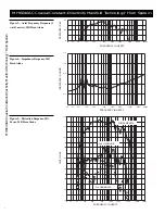
Coaxial Version (see Figure 2):
100 - 20,000 Hz
Non-Coaxial Version (see Figure 3):
100 -4,000 Hz
Low-Frequency 3-dB-Down Point:
150 Hz
Usable Low-Frequency Limit
(10-dB-Down Point):
100 Hz
Average Efficiency:
25%
Long-Term Average Power Handling
Capacity per EIA RS-426A
(see Power Handling section):
600 watts
Maximum Long-Term Mid-Band
Acoustic Output:
150 watts
Sensitivity, 1 Watt (into nominal
impedance) at 1 Meter, Anechoic
Environment, Band-Limited Pink-
Noise Signal:
107 dB
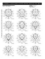
Dispersion Angle Included by 6-dB-
Down Points on Polar Responses,
Indicated One-Third-Octave Bands of
Pink Noise,
200 Hz to 20,000 Hz, Horizontal
(see Figure 6):
60° (+10°, –30°)
315 Hz to 20,000 Hz, Vertical
(see Figure 6):
40° (+20°, –15°)
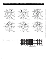
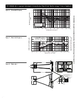
Directivity Factor R
q
(Q), 500 Hz–
20,000 Hz Median (see Figure 7):
24.0
Directivity Index D
i
(10 log R
q
), 500
Hz to 20,000 Hz Median (see Figure
7):
13.8 dB (+0.9, -1.1 dB)
Transducer Complement:
Two DL10X-SH manifold drivers
with Kevlar
®
epoxy composite cones
1
System Impedance, Drivers in Paral-
lel, Nominal/Minimum (mid-bass
section):
8.0/5.9 ohms
Polarity:
A positive voltage applied to the
positive (+) sides of the DL10X-SH
input cables produces a positive
acoustic pressure in the horn throat
Construction,
Main Horn Bell and Driver Back
Covers:
One-piece black polyester and
fiberglass laminate with composite
reinforcement
Hanging Hardware:
Integral black 10-gauge polyester
powder-coated steel
Mechanical Driver Protection:
Integral grille/protection screen
built into the manifold chamber
Coaxial Horn Supplied (mounted in
horn mouth on two steel rails):
HP640
High-Frequency Drivers and Driver-
Manifold Systems for Coaxial HP640
Horn (contractor selected and in-
stalled):
DH1A, DH1A/2MT, DH2A, DH2A/
4MT, N/DYM
®
1 and N/DYM
®
1/2MT
Input Connections,
DL10X-SH:
Heavy-duty 12-AWG oxygen-free
copper cable, unterminated, in exte
rior grade UV-stabilized flexible
conduit
High-Frequency Driver(s):
Heavy-duty 12-AWG oxygen-free
copper cable, unterminated, in exte-
rior grade UV-stabilized flexible
conduit
Recommended Crossover,
Frequency:
1,250 Hz
Slope:
24 dB per octave
Recommended High-Frequency
Driver Delay:
2.96 msec ±0.3 ms
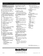
Dimensions (see Figure 8),
Height:
149.9 cm (59.0 in.)
Width:
99.1 cm (39.0 in.)
Length:
187.3 cm (73.9 in.)
Packed Length:
203.2 cm (80.0 in.)
Weight:
75 kg (165 lb)
2
Shipping Weight:
80 kg (176 lb)
Packing:
Wooden pallet
______________
1. Kevlar
®
is a registered trademark of Du Pont.
2. Without high-frequency drivers (see Installation section).


