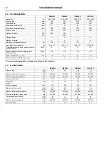


26
Installation manual
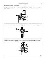
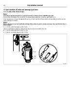
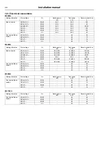
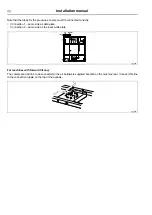
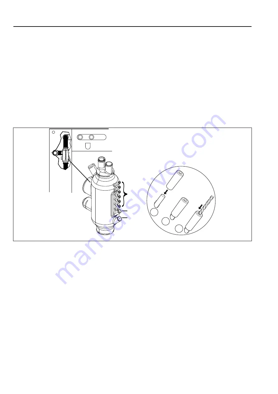
11 Connection of external dosing systems
11.1 Connection of the hoses
Note!
All external equipment which is connected to the machine must be CE/EMC-approved.
The machine is prepared for connection of external dosing systems or water re-use systems etc.
The connections are closed at delivery. Open any of the connections that shall be used by drilling a hole where the
hoses shall be connected.
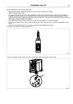
Note!
Make sure there is no burrs left after drilling. When removing burrs make sure burrs does not fall into the si-
phon breaker.
A =
⌀
10 mm (outer dimension), drill
⌀
5 mm
Use the enclosed template by putting it over the connection and drill in the hole.
B =
⌀
16 mm (outer dimension), drill
⌀
11 mm
C =
⌀
20 mm (outer dimension), drill
⌀
15 mm
A
B
C
1
2
3
fig.5875C
Summary of Contents for W4 H Series
Page 2: ......
Page 4: ......
Page 39: ......
Page 40: ...Electrolux Professional AB 341 80 Ljungby Sweden www electroluxprofessional com ...


