


Installation manual
39
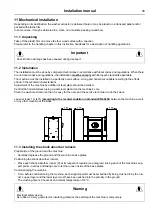
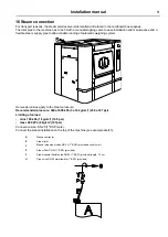
11 Mechanical installation
Depending on its destination, the washer extractor is delivered bare or may be placed on a transport pallet and/or
packed with plastic film.
In some cases, it may be delivered in a crate, or in maritime packing (wood box).
11.1 Unpacking
Take off the plastic film or remove the four wood socles with a spanner..
Please refer to the handling chapter in this instruction handbook for a description of handling operations.
Important
Check that no damage has been caused during transport.
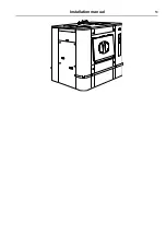
11.2 Installation
The installation must be done by competent technicians in accordance with local codes and regulations. When there
are not local codes and regulations, the installation
must be comply
with European standards applicable.
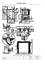
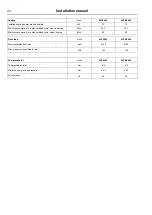
The machine must be installed on a perfectly even surface, strong and horizontal, capable resisting to the efforts
shown in the technical characteristics.
Adjustment of the machine by addition of level plate should be avoided.
Control the horizontal level using a water level placed on the machine's sole.
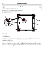
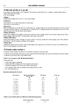
Place the washer extractor so that it is easy for the user and the service technician to do their work.
Leave at least 1 m (40″) (
according to the recommendation in standard EN 60204
) between the machine, a wall
or any other machine at the sides.
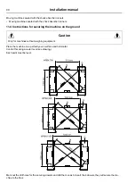
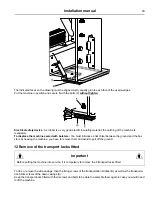
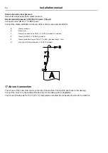
11.3 Installing the shock absorber runners
Preparation of the ground and the machine.
• Carefully degrease the ground and the machine’s base plates.
Positioning the shock absorber runners.
• Place each shock absorber runner (P) at its respective location (see diagram) raising each of the machine’s sup-
port points in series and taking care to let the runner inside of the base plates.
Commissioning the machine
• Time: before commissioning the machine, each support point must be embedded by being crushed in by the run-
ner’s upper layer and the lower layer must have been pushed into the porosity in the ground.
The crushing time is 2 hours at an ambient temperature of 18 °C.
Warning
Electrical safety device.
As rubber is a very good electric insulating material, the earthing of the machine is compulsory.
Summary of Contents for WP4 1100H
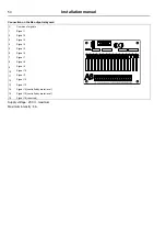
Page 2: ......
Page 4: ......
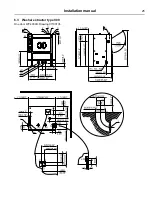
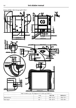
Page 25: ...Installation manual 25 6 3 Washer extractor type 900 One door WP4 900H Drawing 07100138 ...
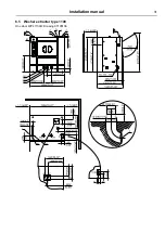
Page 31: ...Installation manual 31 6 5 Washer extractor type 1100 One door WP4 1100H Drawing 07100136 ...
Page 53: ...Installation manual 53 ...
Page 66: ......
Page 67: ......
Page 68: ...Electrolux Professional AB 341 80 Ljungby Sweden www electroluxprofessional com ...


