background image

 52

5954 00U 01

GB

ATTENTION:

The warranty does not cover damage caused by the use of deter-

gents and rinse aids not complying with the above characteristics.


- Detergent and rinse aid containers, independent of the oven, 

must not be placed

 higher than the appliance support surface (for 

model 6 GN they must be placed lower than the oven support top).

Attention: 

Contact with chemical substances (e.g. 

detegent, rinse aid, scale remover, etc.) without 
taking adequate safety precautions. Therefore 
always refer to the safety cards and labels on the 
products used.


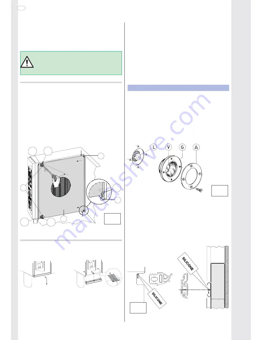
To facilitate oven compartment cleaning, remove the rack trolley 

guides from the bottom of the oven and open the suction wall.
• To open the oven compartment 

suction wall A

 (Fig. 2) proceed 

as follows:

- switch the oven off and disconnect the power to the appliance;

- undo (1a) screw B2 completely with a screwdriver,

- insert the tip of a screwdriver in slot B and prise (1b) inwards to 

open the wall, unhooking it from the pegs B1 at the back.  
If required, 

completely


 remove

 suction wall:

- unscrew (2) nut C1 with a hexagon wrench.

- lift (3) the suction wall and remove it (4) from the bottom pin C 

of the oven compartment;

- lower (5) the wall to release it from the top pin D and completely 

remove it (6).

B2

B

D

C

C1

2

3

4

5

6

A

B2

1b

1a

B1

B1


      2


To re

fi

 t the wall, repeat the steps in reverse order and retighten 

nut C1.

• If present, clean the oven compartment 

grease 

fi

 lter 

(not sup-

plied) at least every three cooking cycles. 

• If present, clean the 

air 

fi

 lter 

(not supplied)


at least once a 

month, removing it from under the 

control panel


1

2

         Removal             

Air fi lter 

                    Fitting

Non-compliance with the above will result in 

fi

 lter inef

fi

 ciency and 

produce anomalous effects in cooking.
• Clean the stainless steel parts every day using lukewarm soapy 

water, rinsing with plenty of water and drying thoroughly.

• Do not clean the stainless steel with steel wool, brushes or 

scrapers in common steel, as they could deposit ferrous particles 

which oxidise, causing rust spots. 

• Whenever the appliance is not used for long periods:

- Disconnect the power supply and close the water and gas cocks;

- go over all steel surfaces vigorously with a cloth moistened with 

paraf

fi

 n oil in order to create a protective 

fi

 lm;

- Periodically air the premises.

6.2 REPLACING CONSUMABLE COMPONENTS

Replacing the oven compartment lamp 

(Fig. 3)

To replace the oven compartment lamp, if burnt out, proceed as 

follows:

• Disconnect the power to the appliance.

• Undo the 4 screws 

fi

 xing the light 

fi

 tting ring nut "A" and remove 

the glass "V" together with seal "G".

• Remove the halogen lamp "L" and replace it with another one 

having the same characteristics (12V - 10W - 300°C), using a 

clean cloth or paper to avoid direct contact with 

fi

 ngers.

• Re

fi

 t the protection glass, correctly inserted inside the seal, in 

the lamp compartment and 

fi

 x the ring nut by retightening the 4 

screws, after smearing the seal with food-grade silicone grease.


      3


Replacing door seals 

(Fig. 4)

NB

: The door seal is a component that can become worn over 

time. It is advisable to replace it whenever any hardening or 

breakage is noticed.

To replace it, proceed as follows:

• Remove the seal from its seat and clean the latter of any traces 

of silicone.

• Apply a bead of silicone sealant at point 

1

 along the inside pro

fi

 le 

of the seal seat.

• Insert the new seal along the entire seat.


   4


Summary of Contents for 236200

Page 1: ...PERATION CHECK 37 7 MAINTENANCE 37 8 BRIEF TROUBLESHOOTING GUIDE 37 9 POSITIONING OF MAIN COMPONENTS 37 III OPERATING INSTRUCTIONS 38 1 OVEN DOOR OPENING 38 1 1 6 AND 10 RACK MODEL 38 1 2 20 RACK MODEL 38 2 Oven door closing 38 2 1 6 AND 10 RACK MODELS 38 2 2 20 RACK MODELS 38 3 DESCRIPTION OF CONTROL PANEL m 39 3 2 MAIN FUNCTIONS AND SYMBOLS 39 OVEN USE 42 4 CONTROL PANEL USE 42 4 1 SWITCHING THE...

Page 2: ...alificationareallowed to install commission and service this product WARNING Failure to use a qualified authorised installer WILL INVA LIDATE THE WARRANTY conditions and may render the appliance inoperative Ifanydoubtpleaseconsultthemanufacturerforfurtheradvice Under no circumstances must this product be used unless installed and or commissioned by a qualified engineer I GENERAL CHARACTERISTICS 2 ...

Page 3: ... this appliance while it is in operation Never check for leaks with an open flame The appliance is not suitable for a marine environment 3 1 PERSONAL PROTECTION EQUIPMENT Give below is a summary table of the Personal Protection Equipment PPE to be used during the various stages of the machine s service life X Safety footwear Protective garments Gloves Ear protectors Mask Safety helmet Stage Transp...

Page 4: ...KING All the packing materials are environmentally friendly They can be stored without risk or burned in a special waste incineration plant Recyclable plastic components are marked as follows polyethylene outer wrapping instructions bag gas PE nozzle bag polypropylene roof packing panels straps pp polystyrene foam corner protectors PS 4 2 USE Our appliances are designed and optimised with laborato...

Page 5: ...h contact opening distance of at least 3 mm must be installed ahead of the appliance This switch must be installed in the building s permanent electrical system in the immediate vicinity of the appliance A device interlocked plug lockable switch or similar devices lockableintheopenpositionduringmaintenancemustbeinstalled ahead of the appliance Appliance max leakage current is 5 mA Theappliancemust...

Page 6: ...tenance Attention Dispensers of substances for preventing scale in the pipes e g polyphosphate dispensers must notbeusedbecausetheycancompromisecorrect appliance operation WATER CHARACTERISTICS INLET N To guarantee correct appliance operation several water treatmentsystemsmayhavetobeinstalled Forthatpurpose see the instructions of the following Flow Chart 5 f 5 f Hardness appraisal Water system re...

Page 7: ...f interruption Automatic reset thermal device inside the fan which is acti vated if the fan overheats protecting unit operation it cuts off the electrical power to the appliance 6 OPERATION CHECK Switch the appliance on as described in the section Operating instructions Explain appliance operation routine maintenance and cleaning operations to the user with the help of the instruction handbook Att...

Page 8: ...nside the oven during operation The maximum height at which the trays are placed in the oven must not exceed 1 6 m This applies if installed according to the instructions and using original accessories except for stacked ovens In case of stacked ovens or in any other case when the above distance is exceeded the following sticker supplied must be placed on the front of the oven in a visible positio...

Page 9: ...okingcycle seesymbol MM SS or Digital thermometer thermostat for control of product core tempe rature CookingwithECO DELTA forcookinglargepieces offood atleast5kg e g wholeturkey legofpork etc Inthiscookingmodeatemperaturesettingofbetween 1 C and 120 C is selected In this case cooking is moderate and long since the COMPARTMENT temperature is automatically adjustedaccordingtothetemperatureinsidethe...

Page 10: ...ired time Multitimer for setting cooking of foods at the same temperature but at different times max 14 MULTIPHASE Cooking with phases in sequence for setting cooking programs with several phases in automatic sequence max 15 phases Active pause phase Add pause phase by entering a time value in this mode it is possible to delay the start of cooking pro grams or include a pause between two cycles e ...

Page 11: ...eovenconfigurationtodefaultvalues Reset Identity Card Oven identification giving rating data and software version This item is located in the Set tings drawer Drawer Thedrawerisanexpansionlocatedinsideseveralenvironmentsof the menu and contains options that are useful in some functions Technical assistance ...

Page 12: ...nctions menu to simplify use and can be customised as required by adding or removing some functions The touch screen has a similar use to that of a cell phone and computer with drop down menu and keypad for entering values In some cases by touching the required symbol a screen relevant to the symbol appears and in others only the function is selected TOUCH the required part of the Display to perfo...

Page 13: ...n close the door to start cooking In case of AUTOMATIC START just close the door to automati cally start the cycle After about 10 seconds the following Cooking in Progress screen will appear Convection 160 2 17 2 30 Phase 2 3 3 Cooking PHASE 2 of 3 Hot Air cycle in progress HUMIDIFICATION in progress Set TEMPERATURE TIME in progress set TIME HALFSPEEDinprogress example InPROGRAMMEDmode theword Con...

Page 14: ...ancel it just touch the same button again To return to the initial setting select another cycle and return to the same Cooling it is possible to set an oven compartment cooling temperature to be reached which will be indicated with the corresponding symbol on the cooking in progress screen Compartment cooling therefore occurs manually and is done outside the cooking cycle cycle HOT AIR HUMIDIFICAT...

Page 15: ...re shows phase 1 with the following settings 1 phase number Hot Air cycle 5 humidification 160 temperature C 0 30 cooking phase time 0 hours 30 minutes Also one or more phases can be skipped during cooking press the symbol next to phase 3 ex in figure to go to this 50 50 225 0 45 3 The Multiphase also has special phases such as Pause for setting a pause between cooking cycles Maintaining cycle wit...

Page 16: ...n order to always be higher than that in the core of the product 20 70 120 0 TEMPERATURE C compart ment core probe Δ T Eco Delta 50 C TIME The graph shows an example with a set Delta of 50 C where the compartment temperature increases keeping this difference of 50 C constant with respect to the core probe This type of cooking is slower than the conventional cooking method but has the advantage of ...

Page 17: ...ss the START button 2 Stopping the cycle When the required product core tempe rature is reached the oven stops automatically and the elapsed cooking cycle time is displayed 3 Core probe mode deactivation Set a cooking time on the Timer This action automatically cuts out the core probe whereas it is the opposite when the time is set The core probe mode is also deactivated when the oven is switched ...

Page 18: ...e e g UI40_01 prg Wait for completion of the loading process Attention Recipes programs with the same name will be overwritten 5 Press OK and remove the key SAVE recipes programs from Oven on USB 1 Insert the USB key 2 Access the Programs menu 3 Open the drawer and select the symbol save on USB Wait for completion of the save procedure 4 Press OK and remove the key 4 6 CLEANING CLEANING SYSTEM Thi...

Page 19: ... Phase Reduce Water Consumption The Green Spirit Economizer function enablesuseofthecleaningprogramsinrespect for the environment If Skip Rinse Aid is selected remember that the traces of scaling could remain in the compartment after cleaning For Skip Drying Phase it is necessary to open the door after cleaning to air the oven For Reduce Water Consumption make sure an efficient ventilation system ...

Page 20: ...ral Show real and set value Multi phase cooking Delayed start Cooking preheating Timer Temperature dialogs Short cooking MultiTimer cooking Eco delta cooking Hold Default convection temp 70 Default steam temp 70 Probe temp increase Δ5 Default cycle PROGRAMS Enable Programs Abilita salvataggio Programmi Enable Programs save CLEANING Enable Cleaning Force after 0 00 of cooking Default cycle Soft Med...

Page 21: ...rine bleach hydro chloric acid etc even if diluted to clean the steel parts Do not use corrosive substances e g muriatic acid to clean the floor under the appliance MAINTENANCE INSPECTIONS CHECKS AND CLEANING FREQUENCY Routine cleaning Daily General cleaning of machine and surrounding area Mechanical protection devices Monthly Check condition and for any deformation loosening or removed parts Cont...

Page 22: ...l 1 2 Removal Air filter Fitting Non compliance with the above will result in filter inefficiency and produce anomalous effects in cooking Clean the stainless steel parts every day using lukewarm soapy water rinsing with plenty of water and drying thoroughly Do not clean the stainless steel with steel wool brushes or scrapers in common steel as they could deposit ferrous particles which oxidise ca...

Page 23: ...he CLEANING SYSTEM rotating jet Fig 6 It is advisable to clean the jet in case of long periods of CLEANING SYSTEM disuse difficulty in wash arm rotation probable nozzle obstruction use of very hard water If the nozzles are completely obstructed use the tip of a knife to remove any encrustations Extract without removing the retaining clip A from the middle block of the jet For this operation insert...

Page 24: ...54 5954 00U 01 GB ...

Reviews: