


114
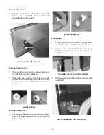
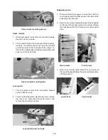
2. The starter base is mounted into the left bracket
that holds the electronic oven control by two plastic
tabs.
3. Disconnect the wires and squeeze plastic brackets.
Starter base
Ballast:
1. Disconnect power from range and remove the
backguard glass.
2. The ballast is held to the splasher panel by one screw
and a tab. To remove the ballast disconnect the wires,
remove the screw and slide the ballast sideways.
Ballast screw
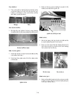
Oven light and fluorescent light switches:
The oven light and fluorescent switches are snapped into
the top of the backguard trim.
1. Disconnect power from range and remove the
backguard glass.
2. Disconnect the wires from the switch, squeeze the
spring load clips on the end of the switch, and push
it through the trim.
Light switch spring clips
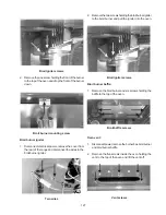
Backguard trim:
1. Disconnect power from range and remove the
backguard glass.
2. The trim is held to the splasher panel in front by two
screws, one in each low corner.
Backguard screw in each corner
3. The trim is held to the back panel of the backguard
by eight screws, three on each side and two across
the top.
Summary of Contents for 30" GAS FREESTANDING RANGES
Page 43: ...43 SAMPLE SCHEMATIC FOR ES100 CONTROL SYSTEM ...
Page 50: ...50 SAMPLE SCHEMATIC FOR ES 200 CONTROL SYSTEM ...
Page 60: ...60 SAMPLE SCHEMATIC FOR ES 300 CONTROL SYSTEM ...
Page 72: ...72 SAMPLE SCHEMATIC FOR ES 400 CONTROL SYSTEM ...
Page 84: ...84 SAMPLE SCHEMATIC FOR ES 450 CONTROL SYSTEM ...
Page 93: ...93 Sample schematic for 36 gas range ...
Page 130: ...130 NOTES ...
Page 131: ...131 NOTES ...
Page 132: ...132 ...


