


117
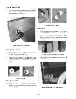
Top burner:
1. The top burners are held to the top burner brackets
by one screw. To remove a burner, lift the main top,
remove the burner screw and lift the burner off the
spud.
Burner screw
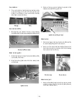
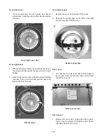
Top burner igniter:
1. The top burner igniters are held to the top burner
brackets by one screw, but their wires run under the
burner box. To replace the left side and griddle burner
igniter lift the main top, remove the cover from the
rear of the range to gain access to the spark module.
Remove the screw holding the igniter to the burner
bracket and slide the igniter sideways. With the
igniter removed from the bracket, cut the wire as
close to the igniter as possible. Tape the end of the
wire on the replacement igniter to the end of the wire
of the original. Using the original wire pull the wire
for the replacement igniter through to the spark
module.
Igniter screw
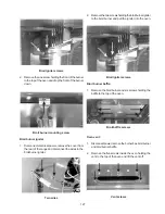
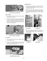
2. One igniter tip from the griddle is connected to the
igniter for the righthand burners. Since the
replacement wire has an igniter on each end the
wire cannot be cut.
3. To replace these igniters, remove the right hand
bodyside, push the igniters down through the burner
box, reach under the burner box through the opening
made by the removal of the bodyside and pull the
igniters out.
Igniter wire
4. To install the igniters push the igniters up through
the burner box holes, slip them into their brackets
and screw the igniter brackets to the burner brackets.
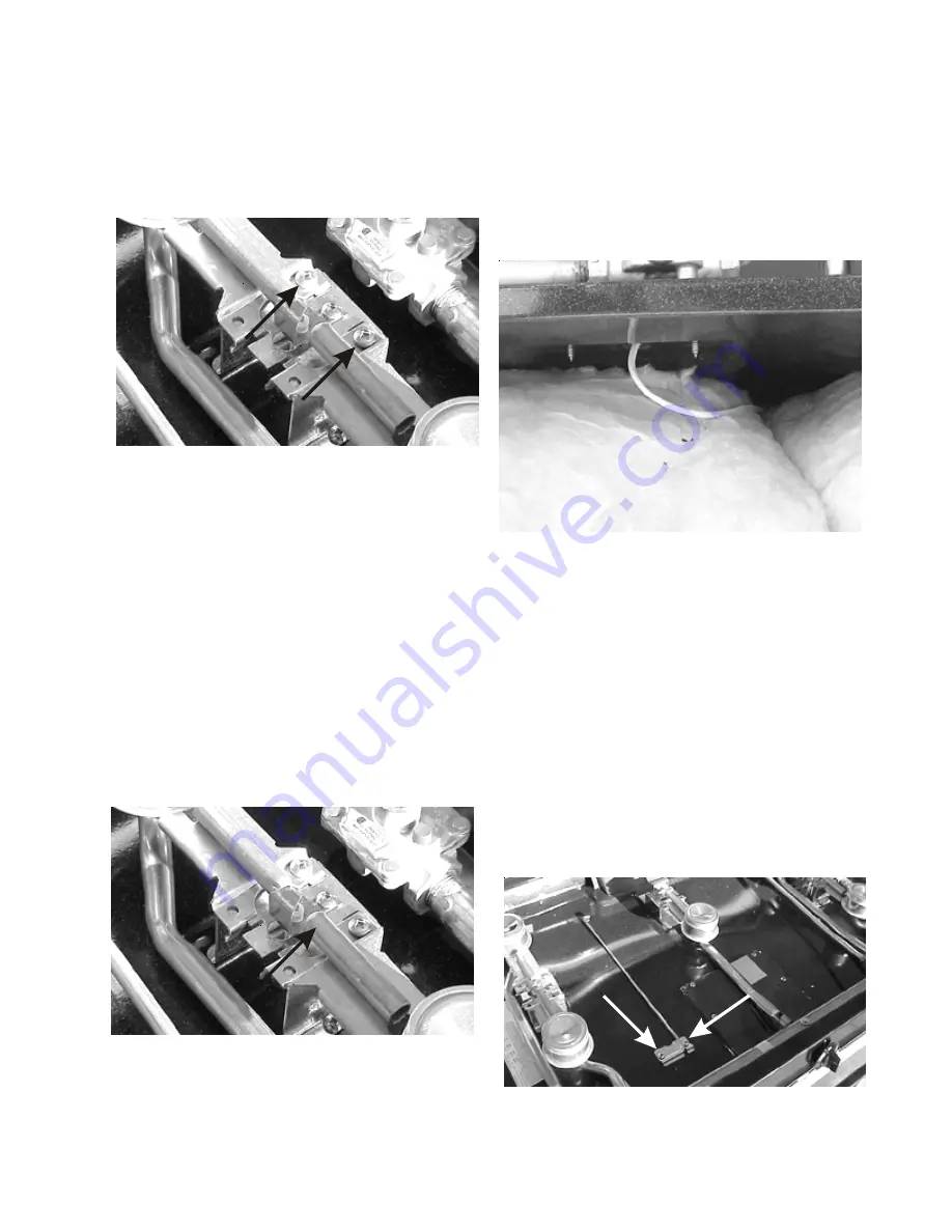
Main top support rod:
1. A support rod is provided to hold the main top in the
raised position. The rod is held to the burner box by
a bracket and two screws.
2. To remove the support rod remove the main top and
remove the two screws holding the bracket to the
burner box.
Support rod and bracket screws
Summary of Contents for 30" GAS FREESTANDING RANGES
Page 43: ...43 SAMPLE SCHEMATIC FOR ES100 CONTROL SYSTEM ...
Page 50: ...50 SAMPLE SCHEMATIC FOR ES 200 CONTROL SYSTEM ...
Page 60: ...60 SAMPLE SCHEMATIC FOR ES 300 CONTROL SYSTEM ...
Page 72: ...72 SAMPLE SCHEMATIC FOR ES 400 CONTROL SYSTEM ...
Page 84: ...84 SAMPLE SCHEMATIC FOR ES 450 CONTROL SYSTEM ...
Page 93: ...93 Sample schematic for 36 gas range ...
Page 130: ...130 NOTES ...
Page 131: ...131 NOTES ...
Page 132: ...132 ...