


129
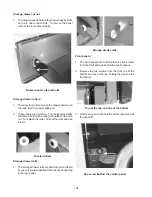
Bodyside panels:
1. Disconnect electrical power, remove the main top,
control panel and front filler panel on the side of the
bodyside to be removed.
2. Remove five screws holding the back of the bodyside
to the rear of the range and and one screw holding
the bodyside to the front frame in the control panel
area.
Rear screws
Front screw
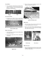
3. Remove one screw at the lower front, one screw at
the top of the panel holding the nylon main top locator.
Lift the panel off.
Lower front
Top bracket
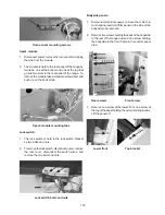
Oven sensor mounting screws
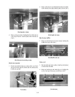
Spark module:
1. Disconnect power, remove the rear cover and unplug
the wire from the module.
2. The module is held to the rear panel of the range by
two tabs, one at the bottom and one at the top that
go into two slots in the rear panel of the range. To
remove the module take a standard screw driver and
push up on the bottom tab.
Spark module mounting tabs
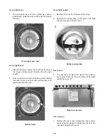
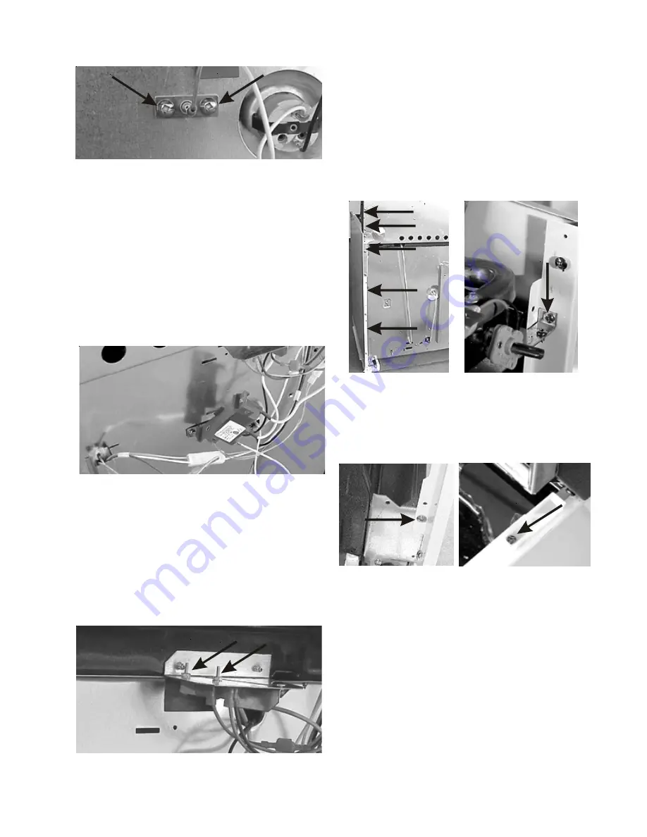
Lock switch:
1. The lock switch is held to the lock switch bracket
by two bolts and nuts.
2. To remove the lock switch, disconnect power, remove
the rear cover, disconnect the switch wires, and
remove the two bolts and nuts.
Lock switch bolts and nuts
Summary of Contents for 30" GAS FREESTANDING RANGES
Page 43: ...43 SAMPLE SCHEMATIC FOR ES100 CONTROL SYSTEM ...
Page 50: ...50 SAMPLE SCHEMATIC FOR ES 200 CONTROL SYSTEM ...
Page 60: ...60 SAMPLE SCHEMATIC FOR ES 300 CONTROL SYSTEM ...
Page 72: ...72 SAMPLE SCHEMATIC FOR ES 400 CONTROL SYSTEM ...
Page 84: ...84 SAMPLE SCHEMATIC FOR ES 450 CONTROL SYSTEM ...
Page 93: ...93 Sample schematic for 36 gas range ...
Page 130: ...130 NOTES ...
Page 131: ...131 NOTES ...
Page 132: ...132 ...


