


17
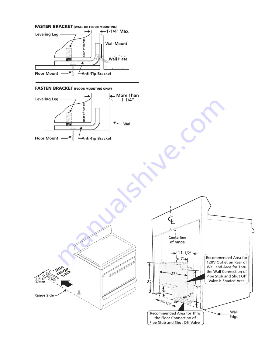
C. Level and Position Range
Level range by adjusting the (4) leveling legs with a
wrench. Note: A minimum clearance of 1/8" is
required between the bottom of the range and the
leveling leg to allow room for the bracket. Use a spirit
level to check your adjustments. Slide range back
into position. Visually check that rear leveling leg is
inserted into and fully secured by the Anti-Tip
Bracket by removing lower panel or storage drawer.
For models with a warmer drawer or broiler
compartment, grasp the top rear edge of the range
and carefully attempt to tilt it forward.
2. Provide an adequate gas supply.
This unit is pre-set to operate on 4" natural gas manifold
pressure. A convertible pressure regulator is connected
to the manifold and MUST be connected in series with
the gas supply line. If the LP/Propane conversion kit has
been used, follow instructions provided with the kit for
converting the pressure regulator to LP/Propane use.
Care must be taken during installation of range not to
obstruct the flow of combustion and ventilation air.
For proper operation
, the maximum inlet pressure to
the regulator should be no more than 14 inches of water
column pressure. The inlet pressure to the regulator
must be at least 1 inch greater than regulator manifold
pressure. Examples: If regulator is set for natural gas
4 inch manifold pressure, inlet pressure must be at
least 5 inches; if regulator has been converted for LP/
Propane gas 10 inch manifold pressure, inlet pressure
must be at least 11 inches.
Leak testing of the appliance shall be conducted
according to the instructions in step 4g.
The gas supply line should be 1/2" or 3/4" I.D.
3. Seal the openings.
Seal any openings in the wall behind the range and in the
floor under the range after gas supply line is installed.
Summary of Contents for 30" GAS FREESTANDING RANGES
Page 43: ...43 SAMPLE SCHEMATIC FOR ES100 CONTROL SYSTEM ...
Page 50: ...50 SAMPLE SCHEMATIC FOR ES 200 CONTROL SYSTEM ...
Page 60: ...60 SAMPLE SCHEMATIC FOR ES 300 CONTROL SYSTEM ...
Page 72: ...72 SAMPLE SCHEMATIC FOR ES 400 CONTROL SYSTEM ...
Page 84: ...84 SAMPLE SCHEMATIC FOR ES 450 CONTROL SYSTEM ...
Page 93: ...93 Sample schematic for 36 gas range ...
Page 130: ...130 NOTES ...
Page 131: ...131 NOTES ...
Page 132: ...132 ...


