


29
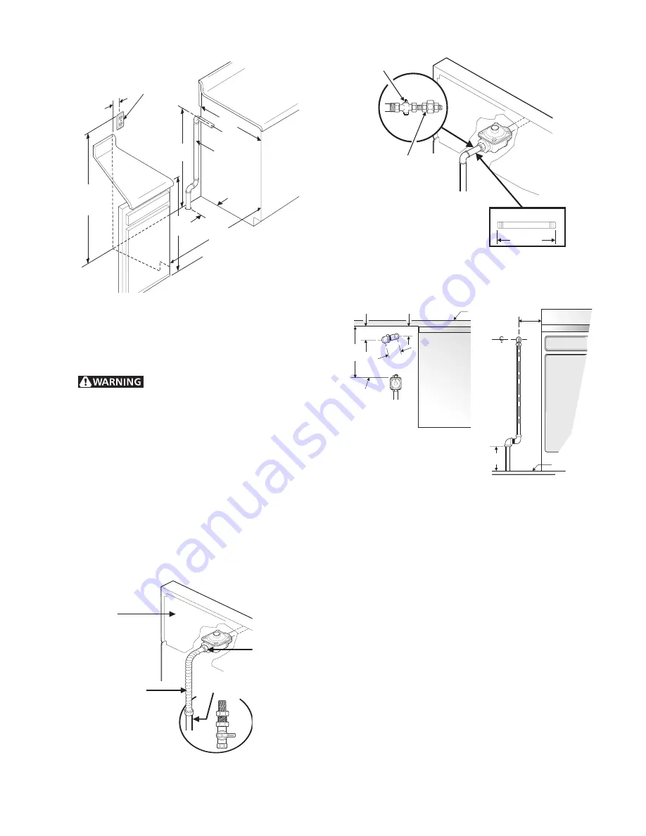
Figure 4
Recommended locations for installing the electrical
outlet and pipe opening may be adjusted to meet
specific requirements.
Do not use a flame to check for
leaks from gas connections. Checking for leaks with
a flame may result in a fire or explosion.
Disconnect this range and its individual shutoff
valve
from the gas supply piping system during any
pressure testing of that system at test pressures
greater than 14" of water column pressure (approx.
½” psig).
Isolate the range from the gas supply piping
system
by closing its individual manual shutoff
valve during any pressure testing of the gas supply
piping system at test pressures equal to or less than
14" of water column (approx. ½” psig).
Solid Pipe Hookup Detail
Figure 7
5. LP/Propane Gas Conversion
A. Pressure Regulator Conversion
Do Not Remove the Pressure Regulator
Remove cap-screw and snap out the nylon gas
indicator by pushing it sideways. Turn the nylon
gas indicator for type gas (Natural or LP) and
snap it back in the cap-screw. Put cap-screw
back on gas regulator.
32
7
/
8
" ± ¼"
3-Wire Polarized
120V. Outlet
3"
25"
36"
20"
or Lower
Gas Supply
Pipe
36 ¼"
6 ¾"
Flexible Connector Hookup
Figure 5
½
" Close Nipple
Flexible
Connector
Back of
Range
Recommended Shut-Off
Location
Solid Pipe Hookup
Figure 6
Shut-Off Fitting
6
3
/
8
"
½" Nipple
Union
Back of
Range
1
7
/
16
"
3 ¾"
¾"
6"
End of
Pressure
Regulator
Counter
Top
TOP VIEW
Wall
Manifold
Floor
FRONT VIEW
2
5
/
8
"
±¼"
11 ½"
Summary of Contents for 30" GAS FREESTANDING RANGES
Page 43: ...43 SAMPLE SCHEMATIC FOR ES100 CONTROL SYSTEM ...
Page 50: ...50 SAMPLE SCHEMATIC FOR ES 200 CONTROL SYSTEM ...
Page 60: ...60 SAMPLE SCHEMATIC FOR ES 300 CONTROL SYSTEM ...
Page 72: ...72 SAMPLE SCHEMATIC FOR ES 400 CONTROL SYSTEM ...
Page 84: ...84 SAMPLE SCHEMATIC FOR ES 450 CONTROL SYSTEM ...
Page 93: ...93 Sample schematic for 36 gas range ...
Page 130: ...130 NOTES ...
Page 131: ...131 NOTES ...
Page 132: ...132 ...


