32
G. Connect Electricity to Gas Range
Electrical Requirements
120 volt, 60 Hertz, individual, properly grounded and
polarized branch circuit protected by a 15 amp. cir-
cuit breaker or time delay fuse.
Extension Cord Cautions:
Because of potential safety hazards under certain
conditions we strongly recommend against the use
of any extension cord. However, if you still select to
use an extension cord, it is absolutely necessary
that it be a UL listed 3-Wire grounding type appli-
ance extension cord and that the current carrying
rating of the cord in amperes be equivalent to or
greater than the branch circuit rating. Such exten-
sion cords are obtainable through your local ser-
vice organization.
Grounding Instructions
IMPORTANT
Please read carefully.
For personal safety, this appliance must be
properly grounded.
The power cord of this appliance is equipped with a
3-prong (grounding) plug which mates with a stan-
dard 3-prong grounding wall receptacle (see Figure
16) to minimize the possibility of electric shock haz-
ard from the appliance.
The wall receptacle and circuit should be checked
by a qualified electrician to make sure the recep-
tacle is properly grounded.
Where a standard 2-prong wall receptacle is in-
stalled, it is the personal responsibility and obliga-
tion of the consumer to have it replaced by a prop-
erly grounded 3-prong wall receptacle.
Do not, under any circumstances,
cut or remove the third (ground) prong from the
power cord.
Disconnect electrical supply cord from wall recep-
tacle before servicing range.
H. Check Operation
Refer to the Use and Care Guide packaged with the
range for operating instructions and for care and
cleaning of your range.
Do not touch the burners. They may be hot enough
to cause burns.
1. Check the igniters
Operation of electric igniters should be checked af-
ter range and supply line connectors have been
carefully checked for leaks and range has been
connected to electric power.
Note
: If range is to be operated on L.P. gas, con-
version of regulator and adjustment of burner
spuds is necessary before ignition check.
a) Surface Burner Igniters
To check for proper lighting, push in and turn a
surface burner knob to the LITE position. The
surface burner should light when gas is avail-
able to top burner. Each burner should light
within 4 seconds in normal operation after air
has been purged from supply lines. Once the
burner lights, knob should be rotated out of the
LITE position. Try each valve separately until
all burners have been checked out.
b) Oven Igniter System
Self-Clean Models - Remove all materials and lit-
erature from oven and:
1. Push the BAKE TEMP button and set the
oven temperature to 300°F. Within 60 sec-
onds the bake (lower) burner will ignite.
Check for proper flame; push the CANCEL
button.
2. Push the broil button and set the oven tem-
perature to 300°F. Within 60 seconds the
broil (upper) burner will ignite. Check for
proper flame. Allow burners to cycle at least
one time; push the CANCEL button.
Figure 16
Preferred Method
Do not, under any
circumstances,
cut, remove, or
bypass the
grounding prong.
Power supply cord with
3-prong grounding plug
Grounding
type wall
receptacle
Summary of Contents for 30" GAS FREESTANDING RANGES
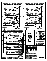
Page 43: ...43 SAMPLE SCHEMATIC FOR ES100 CONTROL SYSTEM ...
Page 50: ...50 SAMPLE SCHEMATIC FOR ES 200 CONTROL SYSTEM ...
Page 60: ...60 SAMPLE SCHEMATIC FOR ES 300 CONTROL SYSTEM ...
Page 72: ...72 SAMPLE SCHEMATIC FOR ES 400 CONTROL SYSTEM ...
Page 84: ...84 SAMPLE SCHEMATIC FOR ES 450 CONTROL SYSTEM ...
Page 93: ...93 Sample schematic for 36 gas range ...
Page 130: ...130 NOTES ...
Page 131: ...131 NOTES ...
Page 132: ...132 ...