background image

Operation of Oven Burners & OvenAdjustments

9. Electric Ignition Burners

Operation of electric igniters should be checked after range and
supply line connectors have been carefully checked for leaks and
range has been connected to electric power.

The oven burner is equipped with an electric control system as
well as an electric oven burner igniter. If your model is equipped
with a waist-high broil burner, it will also have an electric burner
igniter. These control systems require no adjustment. When the
oven is set to operate, current will flow to the igniter. It will "glow"
similar to a light bulb. When the igniter has reached a temperature
sufficient to ignite gas, the electrically controlled oven valve will
open and flame will appear at the oven burner. There is a time
lapse from 30 to 60 seconds after the thermostat is turned ON
before the flame appears at the oven burner. When the oven
reaches the dial setting, the glowing igniter will go off.  The burner
flame will go "out" in 20 to 30 seconds after the igniter goes "OFF."
To maintain any given oven temperature, this cycle will continue
as long as the dial (or display) is set to operate.

Adjust flame until you can quickly turn knob from LITE to
LOWEST POSITION without extinguishing the flame. Flame
should be as small as possible without going out.

Note:

 Air mixture adjustment is not required on surface

burners.

8. Adjust the "LOW" Setting of Surface Burner
Valve (Linear Flow Valves):

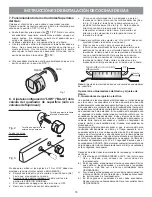
Fig. 1

7. Electric Ignition Surface Burners

Operation of electric igniters should be checked after range and
supply line connectors have been carefully checked for leaks and
range has been connected to electric power.

a.

To check for proper lighting, 

push in and turn

 a surface

burner knob 

counterclockwise

 to the 

(lite)

 position.

You will hear the igniter sparking (See Fig. 1).

b.

The surface burner should light when gas is available to
the top burner.  Purge air from supply lines by leaving

knob in the 

(lite)

 position until burner ignites.   Each

burner should light within four (4) seconds in normal
operation after air has been purged from supply lines.

c.

Visually check that burner has lit. Once the burner lights,

the control knob should be turned out of the  

(lite)

position.

d.

There are separate electrodes (igniters) for each burner.
Try each knob separately until all burner valves have been
checked.

REMEMBER

  —

 DO NOT ALLOW SPILLS, FOOD,

CLEANING AGENTS OR ANY OTHER MATERIAL TO
ENTER THE GAS ORIFICE HOLDER OPENING. 

Always

keep the Burner Caps and Burner Heads in place whenever
the surface burners are in use.

Fig. 2

Test to verify if “LO or LOW” setting should be adjusted (right front

position ONLY):

a.

Push in and turn knob to 

 (lite) until burner ignites.

b.

Push in and quickly turn knob to LOWEST POSITION.

c.   If burner goes out, reset control to OFF.
d.

Remove the burner control knob.

e.

Use a thin-bladed screwdriver and adjust  the inner burner
flame size with the right-hand set screw (See Fig. 2). Adjust
the outer burner flame size with the lower set screw (See Fig.
2). Turn counterclockwise to increase flame size.  Turn
clockwise to decrease flame size.

Test to verify if “LO or LOW” setting should be adjusted (all other

positions):

a.

Follow steps a thru d above.

b.

Insert a thin-bladed screwdriver into the hollow valve stem
and engage the slotted screw inside (Fig. 3) . Flame size can
be increased or decreased with the turn of the screw. Turn
counterclockwise to increase flame size.  Turn clockwise to
decrease flame size.

Inner burner flame

adjustment screw

Outer burner flame

adjustment screw

Right-hand burner only

All other surface burners

Fig. 3

INSTALLATION INSTRUCTIONS FOR FREESTANDING GAS RANGE

7

Summary of Contents for 316469104

Page 1: ...Installation Instructions 30 Free Standing Gas Range Instrucciones de Instalacion Estufa a Gas de 30 316469104 ...

Page 2: ...Anchor ...

Page 3: ... in the vicinity of this or any other appliance WHAT TO DO IF YOU SMELL GAS Do not try to light any appliance Do not touch any electrical switch do not use any phone in your building Immediately call your gas supplier from a neighbor s phone Follow the gas supplier s instructions If you cannot reach your gas supplier call the fire department Installationandservicemustbeperformedbyaqualified instal...

Page 4: ...ed in conjunction with gas ranges other than when the hoodandrangehavebeendesgined testedandlistedby anindependenttestlaboratoryforuseincombinationwith each other Never leave children alone or unattended in the area where an appliance is in use As children grow teachthemtheproper safeuseofallappliances Neverleave the oven door open when the range is unattended Stepping leaning or sitting on the do...

Page 5: ...r the floor or wall When installed to the wall make sure that screws completely penetrate dry wall and are secured in wood or metal When fastening to the floor or wall be sure that screws do not penetrate electrical wiring or plumbing A Locate the Bracket Using the Template Bracket may be located on either the left or right side of the appliance Use the information below to locate the bracket if t...

Page 6: ...be connected in series with the gas supply line Care must be taken during installation of the appliance not to obstruct the flow of combustion and ventilation air For proper operation the maximum inlet pressure to the regulator should be no more than 14 inches of water column pressure The inlet pressure to the regulator must be at least 1 inch greater than regulator manifold pressure Examples If r...

Page 7: ...erpressuredeviceto thetopburnerrightrearorifice Usingarubberhosewithinside diameter of approximately 1 4 hold tubing down tight over orifice Turnburnervalveon Foranaccuratepressurecheckhaveatleasttwo 2 othertop burners burning Be sure the gas supply inlet pressure is at least one inch above specified range manifold pressure The gas supply pressure should never be over 14 water column Whenproperlya...

Page 8: ...e is encountered it is the personal responsibility and obligation of the customer to have it replaced with a properly grounded three prong wall receptacle DONOT UNDERANYCIRCUMSTANCES CUTORREMOVE THETHIRD GROUND PRONGFROMTHEPOWERCORD PLEASE READ CAREFULLY For personal safety this product must be properly grounded GroundingInstructions The power cord of this appliance is equipped with a 3 prong grou...

Page 9: ...urface burner knob counterclockwise to the lite position You will hear the igniter sparking See Fig 1 b The surface burner should light when gas is available to the top burner Purge air from supply lines by leaving knob in the lite position until burner ignites Each burner should light within four 4 seconds in normal operation after air has been purged from supply lines c Visually check that burne...

Page 10: ...r is 1 inch distinct inner blue flame To determine if the oven burner flame is proper remove the oven bottom and burner baffle and set the oven to bake at 300 F To remove the oven bottom remove oven hold down screws at rear of oven bottom Pull up at rear disengage front of oven bottom from oven front frame and pull the oven bottom out of the oven Remove burner baffle so that the burner flame can b...

Page 11: ...presadesuministrodegasdesdeunteléfono en el exterior del edificio Siga las instrucciones que le proporcione la empresadesuministrodegas Sinopudieraponerseencontactoconlaempresadesuministrodegas avisedeinmediatoalcuerpodebomberosdesulocalidad La instalación y cualquier tipo de servicio deberá realizarlo un instalador cualificado una agencia de reparaciones certificada o la empresa de suministro de ...

Page 12: ...amiento Esta cocina requiere aire fresco para que la combustión del quemador sea la adecuada No deben usar las cortinas de aire o cualquier otra campana de ventilación superior que sople aire hacia abajo sobre la estufa a gas a menos que la campana de ventilación y la estufa hayan sido diseñadas probadas y certificadas por un laboratorio de pruebas independiente para el uso combinado de la una con...

Page 13: ...la pared o al suelo Si se instala sujeta a la pared deberá asegurarse de que los tornillos se introducen completamente en la pared seca y se aseguran en madera o metal Cuando sujete la cocina al suelo o a la pared deberá asegurarse de que los tornillos no perforan ningún cable eléctrico o tuberías A Ubicación de la montura con la ayuda de la plantilla la montura puede ubicarse a la izquierda o a l...

Page 14: ...atural de 4 El colector está conectado a un regulador de presión y DEBE conectarse en serie con la línea de suministro de gas Para que el funcionamiento sea adecuado la presión de entrada máxima al regulador no debe ser superior a 14 de presión de columna de agua La presión de entrada al regulador deberá ser al menos 1 más que la presión del colector del regulador Ejemplo Si el regulador se config...

Page 15: ...o posterior derecho del quemador superior Usando una manguera de caucho con un diámetro interior de aproximadamente 1 4 sostenga fuerte la tubería hacia abajo sobreelorificio Enciendalaválvuladelquemador Paraunarevisiónexactadelapresión tengaporlomenosotros dos 2 quemadores superiores Asegúrese que la presión del suministro de gas entrada se encuentra por lo menos una pulgadaporencimadelapresiónes...

Page 16: ...idaddirectaylaobligacióndereemplazarloporun enchufe de pared de tres patillas debidamente cableado a tierra BAJO NINGUNA CIRCUNSTANCIA CORTE RETIRE O DERIVE LA TERCERA PATILLA DE TOMA DE TIERRA DELCABLEDELSUMINISTRODEENERGÍAELÉCTRICA Ajusteelfuegohastaquepuedagirarlaperillademanerarápida desdeLITEhacialaPOSICIÓNMÁSBAJAsinextinguirelfuego El fuego debe ser tan pequeño como sea posible sin apagarlo ...

Page 17: ...ma del quemador desaparecerá por 20 a 30 segundos después que el encendedor se APAGUE Para mantener cualquier temperatura de horno dada este ciclo continuará tanto como el dial o visualizador esté configurado para operar Después de retirar todos los materiales del empaque y la literatura del horno a Fije el horno en HORNEAR BAKE a 300ºF Vea la Guía para Uso y Cuidado para conocer las instrucciones...

Page 18: ...adel quemadordeasadoeslaadecuada elhornoenlaopciónasar Silallamaesdecoloramarillo aumenteeltamañodelaabertura delobturadordeaire Veaeltamaño 2 enelgráficodeabajo Silallamaesdeazulclaro reduzcaeltamañodelaaberturadel obturador de aire Para ajustar un tornillo de cierre flojo vea el gráfico 3 de abajo vuelva a colocar el obturador de aire y ajuste el tornillo de cierre 12 Asegúrese que la cocina est...

Page 19: ...Anchor Anchor ...

Page 20: ......

Reviews: