background image

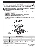
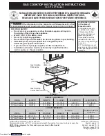
GAS COOKTOP INSTALLATION INSTRUCTIONS

7

Check Operation

Refer to the 

Use and Care Guide

 packaged with the

cooktop for operating instructions and for care and
cleaning of your cooktop.

 Do not touch the burners. They may be

hot enough to cause burns.
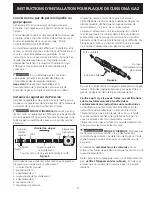
Figure 9

4. Adjust the "LOW" Setting of Regular Burner (see
figure 8) on the Surface Burner Valves (Figure 9):

a. Push in and turn control to LITE until burner ignites.
b.

Quickly 

turn knob to LOWEST POSITION.

c. If burner goes out, reset control to OFF.
d. Remove the surface burner control knob and

decorative ring.

e. Insert a thin-bladed screwdriver into the hollow valve

stem and engage the slotted screw inside. Flame size
can be increased or decreased by turning the screw.
Turn counterclockwise to increase flame size. Turn
clockwise to decrease flame size. Adjust flame until
you can quickly turn knob from LITE to LOWEST
POSITION without extinguishing the flame. Flame
should be as small as possible without going out.

Note:

 Air mixture adjustment is not required on surface

burners.

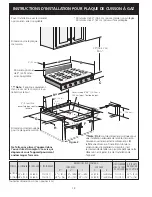
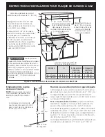
1.  Burner Bases and Burner Caps

This range is equipped with sealed burners as shown
(Figure 8). All pieces are at their place. Take note where
they are. 

Remove all packaging material located

under the Dual Surface burner head.

 Make sure the

burner is properly aligned and leveled.

NOTE

: There are no burner adjustments necessary on

this range.

Figure 8

2.

Turn on Electrical Power and Open Main Shutoff
Gas Valve

3.

Check the Igniters

Operation of electric igniters should be checked after
range and supply line connectors have been carefully
checked for leaks and range has been connected to
electric power. To check for proper lighting:
a.Push in and turn a surface burner knob to the LITE

position. All electronic surface ignitors will spark at the
same time. However, only the burner you are turning
on will ignite.

b.The surface burner should light once the flow of gas

reached the surface burner. Each burner should light
within four (4) seconds in normal operation after air
has been purged from supply lines. Visually check that
burner has lit.

c. Once the burner lights, the control knob should be

rotated out of the LITE position.

There are separate ignition devices for each burner. Try each
knob separately until all burner valves have been checked.

Regular Burner

Burner Cap

Fixed Burner Ring
and Burner Base

Dual Surface

Burner

Burner Base

Fixed Burner Ring

Burner Cap

36” model

30” Model

Summary of Contents for 318201475

Page 1: ...t Installation and service must be performed by a qualified installer service agency or the gas supplier NOTE Wiring diagrams for this cooktop are enclosed in this booklet Figure 1 Gas Cooktop Dimensions Gas Cooktop Cutout Dimensions 30 76 2 cm Min 4 X 4 10 2 cm x 10 2 cm opening to route gas supply 2 5 1 cm Dia Opening to route power cable For Standard Installation 1 2 5 cm 2 5 1 cm 71 4 18 4 cm ...

Page 2: ...ches and cm 30 76 2 cm min for unprotected cabinet and 24 61 cm min for cabinet with protected bottom surface Note D E are critical to the proper installation of the cooktop D reflects the finished dimension Due to the variation in countertop materials it is recommended to first undercut this dimension and then adjust it upon installation of the cooktop Note Applies only in case of countertop back...

Page 3: ...ety Standard title 24 CFR part 3280 Formerly the Federal Standard for Mobile Home Construction and Safety title 24 HUD part 280 or when such standard is not applicable the Standard for Manufactured Home Installation ANSI NCSBCS A225 1 or with local codes where applicable This cooktop has been design certified by CSA International As with any appliance using gas and generating heat there are certai...

Page 4: ...stalled above cooktop 30 76 2 cm min clearance between the top of the cooking platform and the bottom of an unprotected wood or metal cabinet 24 61 cm 30 76 2 cm Min Clearance Between the Top of the Cooking Platform and the Bottom of an Unprotected Wood or Metal Cabinet 24 61 cm Min when Bottom of Wood or Metal Cabinet is Protected by Not Less Than 1 8 Flame Retardant Millboard Covered With Not Le...

Page 5: ...e than 14 35 6 cm of water column W C pressure For checking the regulator the inlet pressure must be at least 1 2 5 cm or 2 5 kPa greater than the regulator manifold pressure setting The regulator is set for 4 10 2 cm of manifold pressure the inlet pressure must be at least 5 12 7 cm The gas supply line to the range should be 1 2 1 3 cm or 3 4 1 9 cm pipe LP Propane Gas Conversion This appliance c...

Page 6: ...o be sure the cooktop manifold pipe has not moved A misalignment could cause the valve stems to rub on the control panel resulting in a gas leak at the valve Disconnect this cooktop and its individual shutoff valve from the gas supply piping system during any pressure testing of that system at test pressures greater than 1 2 psig 3 5 kPa or 14 35 6 cm water column Isolate the cooktop from the gas ...

Page 7: ...hown Figure 8 All pieces are at their place Take note where they are Remove all packaging material located under the Dual Surface burner head Make sure the burner is properly aligned and leveled NOTE There are no burner adjustments necessary on this range Figure 8 2 Turn on Electrical Power and Open Main Shutoff Gas Valve 3 Check the Igniters Operation of electric igniters should be checked after ...

Page 8: ...e size of the outer portion of the dual burner Turn counterclockwise the screw to increase flame size Turn clockwise the screw to decrease flame size Adjust flame until you can quickly turn knob from LITE to LOWEST POSITION without extinguishing the flame Flame should be as small as possible without going out Note Air mixture adjustment is not required on surface burners When All Hookups are Compl...

Page 9: ...ensiones del hueco para la parrilla de cocinar a gas 318201475 0710 Rev D English pages 1 8 Español páginas 9 16 Français pages 17 23 Diagrama de la instalación alámbrica página 24 Todas las dimensiones se dan en pulgadas cm La dimensión F incluye un espacio de 5 por debajo de la plancha de cocinar para la conexión de la línea de suministro de gas NOTA Se adjunta los diagramas de cables de esta pl...

Page 10: ...e sobresalen de la parte inferior de la unidad pueden dañar el acabado inferior del frente Nota D E son críticos para la instalación adecuada de la cocina Por favor asegúrese de respetar estas dimensiones D refleja una dimensión terminada que se recomienda para socavar esta dimensión y ajustar en el momento de la instalación del aparato debido a la variación de los materiales de la cocina Todas la...

Page 11: ...rction and Safet Standard título 24CFR parte 3280 Anteriormente el Federal Standard for Mobil Home Construction and Safety título 24 HUD parte 280 o cuando tal estándar no se aplica el Standard fo Manufactured Home Installation ANSI NCSBCS 225 1 o con los códigos locales El diseño de esta plancha de cocinar cuenta con la aprobación del CSA international Al igual que todos los artefactos a gas que ...

Page 12: ...cho 36 91 4 cm 36 91 4 cm 9 22 9 cm 9 22 9 cm 30 76 2 cm 30 76 2 cm 5 12 7 cm 5 12 7 cm 30 76 2 cm Mínimo de espacio entre la parte superior de la plataforma de la plancha de cocinar y el fondo de una madera non protegida o armario metálico 2 5 1 cm Mínimo distancia entre el borde posterior del hueco y la más cerca superficie combustible por encima del mostrador 24 61 cm 24 61 cm min cuando la par...

Page 13: ...ionamiento 1 válvula de cierre manual 2 boquilla de 1 2 1 3 cm 3 adaptor de 1 2 1 3 cm 4 conector flexible 5 adaptator de 1 2 1 3 cm 6 boquilla de 1 2 1 3 cm 7 regulador de presión Utilice un compuesto de tubo articulado para uso de gas natural y propano para sellar todas las conexiones de gas Si se utilizan conectores flexibles asegúrese que los conectores no están torcidos Provea un adecuado sum...

Page 14: ...cha de cocinar y deberiá estar en un lugar que permita una abertura y cierre fáciles No bloquee las entradas de la válvula de cierre La válvula sirve para abrir o cerrar el paso del gas al artefacto Requerimientos eléctricos Un circuito derivado conectado correctamente a tierra de 120 voltios 60 Herz protegido por un interruptor automático de 15 amp o un fusible de retardo No utilice un cable flex...

Page 15: ...ma puede aumentarse o disminuirse dándole vuelta al tornillo Dé vuelta en sentido opuesto a las manecillas del reloj para aumentar el tamaño de la llama Dé vuelta en sentido a las manecillas del reloj para disminuir la llama Ajuste la llama hasta que usted puede dar vuelta rápidamente a la perilla de la posición LITE a la POSICIÓN MÁS BAJA sin extinguir la llama La llama debe ser tan pequeña como ...

Page 16: ... la porción central del quemador puente o del quemador triple Dé vuelta en sentido opuesto de las manecillas del reloj para aumentar el tamaño de la llama Dé vuelta en sentido a las manecillas del reloj para disminuir la llama Ajuste la llama hasta que usted puede dar vuelta rápidamente a la perilla de la posición LITE a la POSICIÓN MÁS BAJA sin extinguir la llama La llama debe ser tan pequeña com...

Page 17: ...e service d incendie L installation et l entretien doivent être effectués par un installateur qualifié un service d entretien ou de réparation accrédité ou le distributeur de gaz UN INSTALLATEUR QUALIFIÉ DOIT EFFECTUER L INSTALLATION ET LE SERVICE IMPORTANT CONSERVEZ CES INSTRUCTIONS POUR LES INSPECTEURS LOCAUX LISEZ CES INSTRUCTIONS ET CONSERVEZ LES POUR RÉFÉRENCES ULTÉRIEURES Toutes les dimensio...

Page 18: ...ète une dimension finale Étant donné la variation dans le matériel du comptoir il est recommandé de tailler un peu plus petit que cette dimension et l ajuster lors de l installation de l appareil Ouverture de 4 X4 10 2 cm x 10 2 cm pour l entrée de gaz Ne faites pas glisser l appareil dans l ouverture du comptoir Les vis qui dépassent sous l appareil pourraient endommager l armoire Note S applique...

Page 19: ...ment Federal Standard for Mobile Home Construction and Safety titre 24 HUD partie 280 ou en l absence de normes aux normes de la Manufactured Home Installation ANSI NCSBCS A225 1 ou aux codes locaux La conception de cette plaque de cuisson a été approuvée par International Approval Services I A S Il faut prendre certaines précautions d usage lors de l utilisation de tout appareil fonctionnant au g...

Page 20: ...e du dessus du comptoir 24 61 cm Minimum de 24 61 cm lorsque la base de l armoire en bois ou en métal est protégée par un celloderme retardateur de flammes d un minimum de 1 8 recouvert d une feuille de métal MSG No 28 d acier inoxydable d un minimum de 0 015 0 4 mm d aluminium de 0 024 0 6 mm ou de cuivre de 0 020 0 5 mm Dégagement minimum de 30 76 2 cm entre le haut de la surface de cuisson et l...

Page 21: ...tic à joints de tuyaux pur assurer l étanchéité des raccords de gaz naturel et de gaz de pétrole liquéfié Vérifiez que les tuyaux souples de raccordement s il y en a ne sont pas tordus Le tuyau d alimentation doit être équipé d un robinet d arrêt approuvé Ce robinet devrait être situé dans la même pièce que la plaque de cuisson et à un endroit permettant de l ouvrir et de le fermer sans difficulté...

Page 22: ...n électrique de la prise de courant murale avant de réparer ou de nettoyer la plaque de cuisson Installation de la table de cuisson 1 Vérifiez si la table de cuisson est endommagée 2 Si vous installez le dosseret optionnel en acier inoxydable fixez le à l arrière de la table de cuisson à l aide des vis fournies et suivez les instructions fournies avec le dosseret Allez à l étape 3 si vous procédez...

Page 23: ...n LOW sans éteindre la flamme Celle ci devrait être aussi minuscule que possible sans s éteindre Note aucun réglage du mélange d air n est requis sur cette surface de cuisson A B Figure 10 Figure 9 5 Réglez la position LOW des robinets du brûleur de surface double voir Figure 10 Note Sur ce type de valve la position Low de chaque portion doit être réglée individuellement a Appuyez et tournez le bo...

Page 24: ...INSTRUCTIONS D INSTALLATION POUR PLAQUE DE CUISSON À GAZ 24 ...

Reviews: