G
G..1
1..9
9
B
Brriie
eff T
Trro
ou
ub
blle
essh
ho
oo
ottiin
ng
g g
gu
uiid
de
e
Malfunction
Possible causes:
T
Th
he
e p
piillo
ott b
bu
urrn
ne
err d
do
oe
ess n
no
ott lliig
gh
htt..
• The igniter is not properly fixed or connected.
• The piezoelectric ignition or igniter cable are damaged.
• Insufficient pressure in gas pipes.
• Nozzle blocked.
• Faulty gas valve.
T
Th
he
e p
piillo
ott b
bu
urrn
ne
err g
go
oe
ess o
ou
utt w
wh
he
en
n tth
he
e
iig
gn
niitte
err kkn
no
ob
b iiss rre
elle
ea
asse
ed
d..
• The thermocouple is not properly connected or the safety thermostat wires are
disconnected.
• The pilot burner is not heating the thermocouple sufficiently.
• Safety thermostat tripped or faulty.
T
Th
he
e p
piillo
ott b
bu
urrn
ne
err iiss ssttiillll lliitt b
bu
utt tth
he
e m
ma
aiin
n
b
bu
urrn
ne
err d
do
oe
ess n
no
ott lliig
gh
htt..
• Insufficient pressure in gas pipes.
• Blocked nozzle
• Faulty gas valve.
• The thermopile is not being sufficiently heated.
• Faulty operating thermostat.
T
Th
he
e tte
em
mp
pe
erra
attu
urre
e cca
an
nn
no
ott b
be
e a
ad
djju
usstte
ed
d.. • Damaged thermostat bulb.
• Faulty thermostat.
O
Ovve
errtte
em
mp
pe
erra
attu
urre
e
• Filter clogged. Remove the filter to clean (can be placed in a dishwasher).
IIn
nssttrru
uccttiio
on
nss ffo
orr rre
ep
plla
acciin
ng
g cco
om
mp
po
on
ne
en
nttss
(to be carried out only by a specialised installer)
G
Ga
ass vva
allvve
e
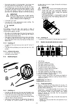
• Remove the control panel, undoing the fixing screws.
• Unscrew the pilot burner pipe and thermocouple.
• Undo the screws fixing the flange to the valve.
• Remove the gas valve supply pipe clamping.
T
Th
he
errm
mo
occo
ou
up
plle
e,, tth
he
errm
mo
op
piille
e,, ssa
affe
ettyy
tth
he
errm
mo
osstta
att,, iig
gn
niittiio
on
n d
de
evviicce
e
• Remove the control panel and replace the elements.
• To replace the thermostat, remove the gasket between the tank and bulb clamping
(replacement from door compartment and control panel).
M
Ma
aiin
n b
bu
urrn
ne
err,, p
piillo
ott b
bu
urrn
ne
err,, p
piillo
ott
n
no
ozzzzlle
e a
an
nd
d m
ma
aiin
n n
no
ozzzzlle
e
• From the door compartment.
M
Ma
aiin
n a
aiirr a
ad
djju
ussttm
me
en
ntt
• From the door compartment.
For installation carry out the same procedure in reverse order.
A
AB
BN
NO
OR
RM
MA
AL
L O
OP
PE
ER
RA
AT
TIIO
ON
N
Any of the following are considered to be abnormal operation and may require servicing:
• incomplete ignition of the burner;
• yellow tipping of the burner flame;
• burner failing to remain alight;
• gas valves are difficult to turn;
• burner extinguished by operation of the fryer door.
In case the appliance fails to operate correctly, contact the authorised service provider in your area.
G
G..1
1..1
10
0 M
Ma
aiin
ntte
en
na
an
ncce
e a
an
nd
d sscch
he
ed
du
ulle
e
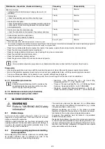
All the components requiring maintenance are accessible from the front or the rear panel of the appliance.
Maintenance frequency
• Machine maintenance, checking and overhaul operations must only be carried out by a specialised Technician or the Customer
Care Service, provided with adequate personal protection equipment (safety shoes and gloves), tools and ancillary means.
• Work on the electrical equipment must only be carried out by a specialised electrician or the Customer Care Service.
• To ensure constant machine efficiency, it is advisable to carry out the checks with the frequency given in the following table:
M
Ma
aiin
ntte
en
na
an
ncce
e,, iin
nssp
pe
eccttiio
on
nss,, cch
he
ecckkss a
an
nd
d cclle
ea
an
niin
ng
g
F
Frre
eq
qu
ue
en
nccyy
R
Re
essp
po
on
nssiib
biilliittyy
Ordinary cleaning
• general cleaning of machine and surrounding area.
Daily
Operator
Mechanical protection devices
• check their condition and for any deformation, loosening or
removed parts.
Yearly
Service
• Control
check the mechanical part, for cracks or deformation, tighten-
ing of screws: check the readability and condition of words,
stickers and symbols and restore if necessary.
Yearly
Service
27


