background image

ENGLI

S

H

33

H

GENERAL SAFETY RULES

H1

Introduction

The machines are provided with electric and/or mechan-
ical safety devices for protecting workers and the 
machine itself. Therefore the user must not remove or 
tamper with such devices.

The Manufacturer declines any liability for damage due 
to tampering or their non-use.

H1.1

Protection devices installed on the machine

H1.1.1

Guards

The guards on the machine are:

-

fixed guards (e.g. casings, covers, side panelling, 
etc.), fixed to the machine and/or frame with screws 
or quick-release couplings that can only be removed 
or opened with tools;

-

interlocked movable guards (front panels) for access 
to inside the machine;

-

access doors to the machine’s electrical equipment, 
made from hinged panels openable with tools. The 
door must not be opened during machine movement, 
if inside the door there is equipment that is hazardous 
when live or under pressure.

H1.1.2

Safety devices

The machine has:

-

a yellow/red main switch that acts as an emergency 
switch;

-

interlocks on the front panels giving access to inside 
the machine;

-

emergency stop push buttons and stops must be 
installed on the rack handling tables in case the racks 
exceed their travel.

H1.2

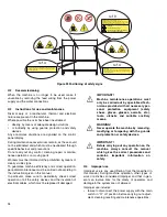
Safety signs to be displayed on the machine

IMPORTANT!

Several illustrations in the manual repre-
sent the machine, or parts of it, without 
guards or with guards removed. This is 
purely for explanatory requirements. 
Never operate the machine without the 
guards or with the safety devices deacti-
vated.

PROHIBITION

MEANING

Do not oil, lubricate, repair and 
adjust moving parts.

Do not remove the safety 
devices.

Do not use water to extinguish 
fires (shown on electrical parts).

DANGER

MEANING

DANGER OF CRUSHING HANDS

DANGER OF BURNS

DANGER OF ELECTROCUTION

(shown on electrical parts with 
indication of voltage).

WARNING!

Do not remove, tamper with or make the 
labels on the machine illegible.

ref. A

ref. B

CAUTION

THI

S

 DI

S

HWA

S

HER HA

S

 MORE THAN ONE POWER-

S

UPPLY

CONNECTION POINT. DI

S

CONNECT ALL POWER 

S

UPPLIE

S


BEFORE 

S

ERVICING.

Doc.No.: 5956.613.00

MINIMUM WA

S

H TEMPERATURE 160°F (71°C)

MINIMUM PUMPED RIN

S

E TEMPERATURE 1

8

0°F (

8

2°C)

MINIMUM 

SANITIZING RINSE TEMPERATURE 180 °F (82 °C)

MAX. CONVEYOR 

S

PEED 5.4

8

 FT./MIN (1.67 M/MIN)

Doc.No.: 5956.5

8

2.00

WARNING

THERE ARE MOVING PART

S

.

THERE I

S

 THE  PO

SS

IBILITY OF 

S

PRAYING

AND 

S

PLA

S

HING OF HOT WATER.

Doc.No.: 5956.5

8

2.00

Summary of Contents for 534074

Page 1: ...STORAGE Page 14 D1 Introduction Page 14 D1 1 Transport Instructions for the carrier Page 14 D2 Handling Page 15 D2 1 Procedures for handling operations Page 15 D2 2 Translation Page 15 D2 3 Placing the load Page 15 D3 Storage Page 15 E INSTALLATION AND ASSEMBLY Page 16 E1 Customer responsibilities Page 16 E2 Characteristics of the site installation Page 16 E3 Machine space limits Page 16 E4 Positi...

Page 2: ... on the machine Page 33 H1 2 Safety signs to be displayed on the machine Page 33 H2 Decommissioning Page 34 H3 Instructions for use and maintenance Page 34 H4 Improper use Page 34 H5 Residual risks Page 35 I NORMAL MACHINE USE Page 36 I1 Correct use Page 36 I2 Characteristics of personnel trained for normal machine use Page 36 I2 1 Characteristics of personnel enabled to operate on the machine Pag...

Page 3: ...Rinse aid connection Page 27 Figure 14 Diagram of curtain positioning on compact machines Page 28 Figure 15 Handling electrical connection system Page 29 Figure 16 Detail of electrical connection Page 29 Figure 17 Examples of dishwasher and rack handling system couplings Page 30 Figure 18 Prewash module tank filters Page 32 Figure 19 Wash rinse module tank filters Page 32 Figure 20 Prewash Page 32...

Page 4: ... various operations for the purpose of avoiding wrong and improper actions that could negatively affect the machine s integrity or endanger persons The manual must always be available to operators and carefully kept in the place where the machine is used so that it is immediately at hand for consultation in case of doubts or whenever required If after reading this manual there are still doubts reg...

Page 5: ...al barrier Safety device a device other than a guard that eliminates or reduces the risk it can be used alone or in combination with a guard Customer the person who purchased the machine and or who manages and uses it e g company entrepreneur firm Emergency stop device a group of components intended for the emergency stop function the device is activated with a single action and prevents or reduce...

Page 6: ...w to identify the technical data To identify the technical data Figure 4 read the factory description of the product F Mod on the dataplate identify the main machine data and consult the Table 1 Main technical characteristics performance and con sumption C1 Main technical characteristics Figure 4 Technical data identification Machine left F Mod WT44BR208 Comm Model WT44BR208 CONFORMS TO ANSI UL 92...

Page 7: ...e and health in the workplace The Manufacturer declines any liability for damage caused by arbitrary modifications and conversions car ried out by the user or the Customer The employer or workplace manager is responsible for identifying and choosing adequate and suitable personal protection equipment to be worn by operators in compli ance with current regulations in the country of use Electrolux P...

Page 8: ... offer practical and easy use for obtaining excellent washing results Rack handling inside the machine occurs automatically The electronic system enables complete supervision of the washing process The control panel also has a display that shows the operating parameters and sig nals any anomalies In this type of machine the rack is taken from the loading point to the unloading point through the va...

Page 9: ...us wash phase Rinsing is carried out with clean water coming from the water system heated to a max temperature of 82 90 C 180 194 F The high temperature ensures satisfactory drying and careful neutralization of bacteria The addition of rinse aid allows the water to easily run off the dishes thus favouring the drying process B2 3 Prewash zone Water is sprayed on the dishes in the prewash zone throu...

Page 10: ...20 20 Electric conductivity of water μS cm 400 400 400 400 Supply water hardness fH dH ppm CaCO3 14 8 140 14 8 140 14 8 140 14 8 140 Rack loading feed RH machine LH machine From right to left From left to right From right to left From left to right From right to left From left to right From right to left From left to right No speeds 2 2 2 2 Capacity speed 1 racks h 100 100 100 100 Capacity speed 2...

Page 11: ...er kW 0 32 0 32 0 32 0 32 current absorbed by pump A 1 5 1 5 1 5 1 5 boiler heating elements with boiler rise 100 kW 6 0 6 0 6 0 6 0 6 0 6 0 6 0 6 0 6 0 6 0 6 0 6 0 6 0 6 0 6 0 6 0 boiler heating elements with boiler rise 70 kW 6 0 6 0 6 0 6 0 6 0 6 0 6 0 6 0 6 0 6 0 6 0 6 0 boiler heating elements with boiler rise 40 kW 6 0 6 0 6 0 6 0 6 0 6 0 6 0 6 0 boiler capacity l gal 12 12 3 17 3 17 12 12 3...

Page 12: ...recognize and avoid any possible haz ard The Manufacturer declines any liability whenever trans port is undertaken by carriers chosen by the Customer D1 1 Transport Instructions for the carrier During the journey the tightness of the fixing systems must be checked several times and in particular just a few km after the start of the journey in case of sudden temperature changes in case of intense c...

Page 13: ... manoeuvre in case of hazardous situations D2 3 Placing the load Before placing the load make sure the path is free and that the floor is flat and can take the load D3 Storage The machine and or its parts must be stored and pro tected against damp in a non aggressive place free of vibrations and with room temperature of between 10 C 14 F and 50 C 122 F The place where the machine is stored must ha...

Page 14: ... size must be increased in case of use and or trans fer of other equipment and or means or if exit routes are necessary inside the workplace E4 Positioning Unless otherwise agreed the machine is supplied in a single unit The machine must be taken to the place of installation and the packing base removed only when being installed Arranging the machine Position the machine in the required place Adju...

Page 15: ...with anti return protection and check valve and stop cock are available as optional accessories If the water hardness exceeds 14 fH 8 dH 10 cH install a softener filter on the dishwasher inlet connection pip ing to ensure efficient machine operation Connect the appliance water supply to the mains fitting a cut off cock a filter and a pressure gauge between the appliance and the mains Figure 8 Wate...

Page 16: ...80 140F 26 60 C C Hot water inlet min 194 F 90 C D Cold water inlet M2 Rinse pump M4 Wash pump M8 Prewash pump ABV Air Break Valve YV1 Filling Air Gap filling solenoid valve 5 28 gal min 20 l min YV5 Wash tank drain solenoid valve YV6 Wash tank water filling solenoid valve 5 28 gal min 20 l min YV9 Prewash tank water filling solenoid valve 5 28 gal min 20 l min YV11 Prewash tank drain solenoid val...

Page 17: ...iler LEGEND A Hot water inlet related to boiler rise B Hot water inlet 80 140F 26 60 C C Hot water inlet min 194 F 90 C D Cold water inlet M2 Rinse pump M4 Wash pump M8 Prewash pump ABV Air Break Valve YV1 Filling Air Gap filling solenoid valve 5 28 gal min 20 l min YV5 Wash tank drain solenoid valve YV6 Wash tank water filling solenoid valve 5 28 gal min 20 l min YV9 Prewash tank water filling so...

Page 18: ...diagram rack type dishwasher 44 left LEGEND A Hot water inlet G 3 4 B Cold water inlet G 3 4 C Drain outlet G 1 1 2 I Power supply entry Q Equipotential screw S Pipe inlet for detergents S1 Detergent probe arrangement ...

Page 19: ...ion diagram rack type dishwasher 44 right LEGEND A Hot water inlet G 3 4 B Cold water inlet G 3 4 C Drain outlet G 1 1 2 I Power supply entry Q Equipotential screw S Pipe inlet for detergents S1 Detergent probe arrangement ...

Page 20: ...diagram rack type dishwasher 66 left LEGEND A Hot water inlet G 3 4 B Cold water inlet G 3 4 C Drain outlet G 1 1 2 I Power supply entry Q Equipotential screw S Pipe inlet for detergents S1 Detergent probe arrangement ...

Page 21: ...ion diagram rack type dishwasher 66 right LEGEND A Hot water inlet G 3 4 B Cold water inlet G 3 4 C Drain outlet G 1 1 2 I Power supply entry Q Equipotential screw S Pipe inlet for detergents S1 Detergent probe arrangement ...

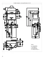
Page 22: ...24 Figure 9 Installation diagram Recommended table connection and fabrication ...

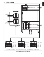
Page 23: ...nnections diagram B A Configuration of the electrical box according to the supply water temperature ELECTRICAL BOX BOILER SUPPLY TERMINAL BOARD BOILER SUPPLY TERMINAL BOARD MACHINE POWER CABLES POWER CABLE Boiler terminal board POWER CABLE Machine terminal board ...

Page 24: ...eing done on that circuit E8 1 Arrangement for water connection Described below are all the possible plumbing connec tions that can be made in the machine for installing detergent or rinse aid dispensing devices IMPORTANT Work on the electrical systems must only be carried out by a qualified electrician IMPORTANT The connection cable must be H07RN F type oilproof IMPORTANT All electrical intervent...

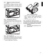
Page 25: ... E8 1 3 Rinse aid dispensers The machine is supplied with a nipple a piece of pipe and two clamps for connecting the rinse aid dispenser Carefully follow the instructions given below to correctly carry out the connection for the rinse aid remove the upper panel B Figure 10 Figure 13 Rinse aid connection connect the rinse aid dispenser pipe unscrewing plug T Figure 13 always paying attention to pot...

Page 26: ...n the version with left rack loading and then in the version with right rack loading Figure 14 Diagram of curtain positioning on compact machines Types of curtains on the machine Double long 1 Quadruple long 2 Single short 3 Important fasten the curtains with the flat part against the hook Rack type dishwasher 44 Rack type dishwasher 66 2 2 3 2 2 3 1 2 3 3 3 3 1 1 1 2 2 2 ...

Page 27: ...f emergency switches If rack handling systems are connected at the infeed or outfeed of a rack type dishwasher install on such sys tems emergency switches that are clearly visible and identifiable and easily accessed by the operator R Figure 17 who must use them Described below are possible couplings of dishwashers L Figure 17 with rack handling systems M with the corresponding positions of the em...

Page 28: ...t its interlock restart the machine according to what is described in par I3 Daily activation of machine Figure 17 Examples of dishwasher and rack handling system couplings IMPORTANT Operators must know the position of the emergency switches installed on the machine The paths to reach and operate them must be kept free of obstacles IMPORTANT Emergency switches must be installed otherwise the machi...

Page 29: ...s speed is recommended for washing medium dirty or not very dirty dishes When a speed is selected the corresponding key is lit Stop This key is used to stop a wash phase or drain cleaning cycle F2 Accessory function selection controls Accessory functions This key is used to access the accessory functions menu which is displayed When activating the accessory functions menu or exe cuting one of thes...

Page 30: ...ms and curtains Make sure the upper and lower prewash Figure 20 wash Figure 21 and rinse Figure 22 arms are cor rectly fitted Also make sure the prewash and wash arm couplings are correctly locked and that the rinse arm ring nuts are secured Figure 22 Rinse Make sure all the types of curtains provided for the machine model are correctly fitted according to that indi cated in par E9 Fitting curtain...

Page 31: ...ergency stop push buttons and stops must be installed on the rack handling tables in case the racks exceed their travel H1 2 Safety signs to be displayed on the machine IMPORTANT Several illustrations in the manual repre sent the machine or parts of it without guards or with guards removed This is purely for explanatory requirements Never operate the machine without the guards or with the safety d...

Page 32: ...operation other types of work or activities considered improper and that in gen eral can involve risks for the safety of operators and damage to the system are not allowed Improper use includes failure to disconnect the power supply with the main switch in O off position before carrying out adjust ment cleaning resetting and maintenance operations CAUTION THIS DISHWASHER HAS MORE THAN ONE POWER SU...

Page 33: ...For the Customer s complete information the residual risks remaining on the machine are given below such actions are to be considered incorrect and therefore strictly forbidden Table 3 Residual risks RESIDUAL RISK DESCRIPTION OF HAZARDOUS SITUATION Slipping or falling The operator can slip due to water or dirt on the floor Catching dragging or crushing Catching or dragging of the operator or other...

Page 34: ... on work hygiene and safety In the event of a significant anomaly e g short circuits wires coming out of the terminal block motor break downs worn electrical cable sheathing etc the opera tor qualified for normal machine use must immediately deactivate the machine by turning the main switch to O or operating the main emergency switch on the machine close the machine water supply by shutting off th...

Page 35: ...emove the rack and load new racks with dirty dishes at the dishwasher infeed I3 2 Rack jamming If the dishes are not correctly loaded on the racks jam ming may occur inside the tunnel and the display shows SEE F Table 2 itEM G Table 2 inSidE H Table 2 Switch the machine off open the doors and eliminate the cause of jamming I3 3 Wash phase stop Press the Stop key B Table 2 to stop the wash phase Wa...

Page 36: ... tray positioned there could collide with the wall of the machine Figure 26 Figure 26 Positioning trays I3 6 Accessory functions To activate an accessory function make sure the machine is not in the wash phase if necessary press the Stop key B Table 2 Press the accessory functions key M Table 2 the accessory functions menu is accessed To quit the accessory functions menu press the acces sory funct...

Page 37: ...le with door open G Table 2 2 wash rinse module 3 prewash module Close all open doors and restore normal dishwasher operation I3 8 Emergency stop When the emergency mushroom push button is acti vated the dishwasher emits an acoustic signal the dis play shows Deactivate the emergency mushroom push button to restore normal dishwasher operation following that given in par E10 4 Emergency stop reinsta...

Page 38: ...re sensor is short circuited 36 The wash tank temperature sensor is open 40 The wash tank was not completely emp tied within the max emptying time 76 The inverter that controls the feeding gear motor has generated an error 77 The inverter that controls the feeding gearmotor has generated an error 82 The required temperature was not reached in the first boiler within the max heating time 83 The wat...

Page 39: ...lean inside the machine making sure to remove any residuals of detergent or food Clean the inside of doors with a damp cloth and detergent At the end of cleaning operations refit the previously removed parts Close the machine door I4 2 Exterior cleaning Clean the stainless steel surfaces with lukewarm soapy water do not use detergents containing abrasive sub stances steel wool brushes or scrapers ...

Page 40: ...oduct should not be treated as domestic waste but must be correctly disposed of in order to prevent possi ble negative consequences for the environment and the human health Regarding the recycling of this product please contact the sales agent or dealer of your product your after sales service or the appropriate waste disposal service I8 Troubleshooting THE DISHWASHER DOES NOT WASH PROPERLY 1 Chec...

Reviews: