background image

Technical Support - A.D.L. 

32/83 

599 74 12-51 Rev.00 


ALA

R

M


CO

DE 

Description 

Possible fault 

Machine status / action Machine status 

Reset 

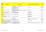
E41 

Door open 

  Check whether the door is closed properly. 

 Faulty 

wiring. 

  Door safety interlock faulty. 

  Main circuit board faulty. 

Cycle paused. 

CLOSE  

THE DOOR 

E42 

Problems with door lock 

 Faulty 

wiring. 

  Door safety interlock faulty. 

  Electrical current leak between heating element and ground. 

  Main circuit board faulty. 

Cycle paused. 

START / 

RESET 

E43 

Faulty triac supplying power to 
door delay system 

 Faulty 

wiring. 

  Door safety interlock faulty. 

  Main circuit board faulty. 

Safety drain cycle. 
Cycle blocked. 

RESET 

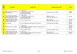
E44 

Faulty “sensing” of door delay 
system 

  Main circuit board faulty. 

Safety drain cycle. 
Cycle blocked. 

RESET 

E45 

Faulty sensing by door delay 
system triac 

  Main circuit board faulty. 

Safety drain cycle. 
Cycle blocked. 

RESET 


E51 

Motor power triac short-circuited 

 Faulty 

wiring. 

 Motor 

faulty. 

  Main circuit board faulty. 

After 5 attempts, cycle blocked with door 
unlocked. 

ON / OFF 

RESET 

E53 

“Sensing” faulty triac motor. Input 
voltage to microprocessor faulty 

  Main circuit board faulty. 

Cycle interrupted. 

RESET 

E54 

Motor relay contacts sticking 
(high voltage level when the relay 
switches to OFF) 

  Current leakage from the motor. 

  Current leakage from the cabling. 

  Main circuit board faulty. 

Cycle blocked with door locked after 5 attempts. 

RESET 


Summary of Contents for 7 Series

Page 1: ...achines with electronic control system EWM09 Technical and functional characteristics NEW COLLECTION SERIES 6 7 ELECTROLUX HOME PRODUCTS Customer Care EMEA Training and Operations Support Technical Support Publication number 599 74 12 51 Edition 03 2011 Rev 00 EN ...

Page 2: ...Technical Support A D L 2 83 599 74 12 51 Rev 00 ...

Page 3: ...ying the alarms to the user 27 8 2 Reading the alarms 28 8 3 Rapid reading of alarms 29 8 4 Deleting the last alarm 29 8 5 Alarm Summary Table 30 9 OPERATING TIME COUNTER 37 9 1 Reading the operating time 37 9 2 Display of total operating time 38 9 3 Description of options 39 9 3 1 Rinse hold 39 9 3 2 Pre wash 39 9 3 3 Pre wash 39 9 3 4 Stains 39 9 3 5 Super rinse 39 9 3 6 No spin 39 9 3 7 Daily 3...

Page 4: ...3 4 Programme selector knob 62 13 5 Cover 63 13 6 Water dispenser 63 13 7 Sides 64 13 8 Electronic pressure switch 64 13 9 Solenoid valves 65 13 10 Air break 65 13 11 Main board 66 13 12 Front panel 67 13 13 Door Lock 67 13 14 Base board 68 13 15 Transport roll 68 13 16 Bellow seal 69 13 17 Inlet 72 13 18 Counterweights 74 13 18 1 Right counterweight 74 13 18 2 Left counterweight 74 13 19 Shock ab...

Page 5: ...EDs and the LCD screen are turned off and the buttons are disabled although the main circuit board and certain electrical components are electrically powered There are two ways of disconnecting the electric power supply the first is to remove the plug or integrate a small electronic circuit known as Zero Watt 0 Watt into the main electronic circuit board that automatically turns off the appliance ...

Page 6: ... 95 4 kit to avoid electrostatic discharges damaging the electronic circuit board see S B Nr 599 72 08 09 Any work on electrical appliances must only be carried out by qualified technicians This platform is not fitted with an ON OFF switch Before you access internal components take the plug out of the socket to disconnect the power supply When replacing the heating element replace it with one that...

Page 7: ... board Inverter No buttons Maximum 7 5 options START PAUSE ON OFF No LEDs Maximum 14 LCD Programme selector 15 positions incorporated in the circuit board Serial port DAAS EAP communication protocol up to 115 200 baud Power supply voltage 220 240 V 50 60 Hz configurable Washing type Traditional with Eco ball Jet System Rinsing system Traditional with Eco ball Jet System Motor Universal Spin speed ...

Page 8: ...gramme switch with 15 positions including the 0 position 14 LEDs Display Positioning of LEDs and buttons Display board assembly exploded view 1 Selector board protection 2 Display board protection 3 LED light diffuser 4 LED light diffuser support 5 Display board and selector board 6 Rear protection ...

Page 9: ...d the washing temperature to be selected according to the type of garments The selector can be turned both clockwise and anti clockwise For each programme the compatible options and other parameters are defined 3 2 4 Programme configuration The table below lists the parameters that can be used to define the washing programmes Types of fabric Cotton Linen Synthetics Delicates Wool Hand wash Shoes J...

Page 10: ... will need to take the plug out of the socket to cut off the electricity supply completely Button no 2 TEMPERATURE It is related to 5 LEDs L1 The starting temperature shown on the LCD display is the one set for the programme selected Press this button in sequence to lower the temperature when the lowest temperature is reached the selection will start again from the highest one available for the pr...

Page 11: ...e lighting turning off of the LED At the same time the programme time is updated via the three digits Button no 6 DELAYED START This button is configurable and has the DELAYED START function During the programme selection phase a delayed start can be selected from 30 to 20 hours 30 60 90 2h 3h 20h 0h and the time is shown on the Display During the last hour the time decreases minute by minute To c...

Page 12: ...pdated minute by minute Selection incorrect Displays the flashing message Err for one second When a function not compatible with the chosen programme is selected or if the selector is turned when a cycle is in progress End of cycle When the cycle ends and you can open the door the display shows a permanently lit 0 Stopping the machine with water in the tub at the end of programmes with the RINSE H...

Page 13: ... PAUSE ON OFF No LEDs Maximum 20 LCD Programme selector 16 positions incorporated in the circuit board Serial port DAAS EAP communication protocol up to 115 200 baud Power supply voltage 220 240 V 50 60 Hz configurable Washing type Traditional with Eco ball Jet System Rinsing system Traditional with Eco ball Jet System Motor Two pole asynchronous three phase with tachometric generator Spin speed 4...

Page 14: ...ax 8 buttons Programme switch with 16 positions without the 0 position 20 LEDs LCD Positioning of LEDs and buttons Display board assembly exploded view 7 Selector board protection 8 Display board protection 9 LCD screen 10 Display board and selector board 11 Rear protection 1 2 3 4 5 ...

Page 15: ...ing cycles e g water level drum movement no of rinses and the washing temperature to be selected according to the type of garments The selector can be turned both clockwise and anti clockwise For each programme the compatible options and other parameters are defined 4 2 4 Programme configuration The table below lists the parameters that can be used to define the washing programmes Types of fabric ...

Page 16: ...selected Press this button in sequence to lower the temperature when the lowest temperature is reached the selection will start again from the highest one available for the programme The temperatures available displayed in C are 95 C 60 C 50 C 40 C 30 C 20 C cold cycle the cold cycle is displayed by three dashes Button no 3 SPIN SPEED This is related to the part of the LCD display in which the was...

Page 17: ...hts up press twice for the Super Quick function the relevant LED will remain on fixed and at the same time the three digit display will vary the cycle time Stains and HOT and COLD Water are alternative options for the same button When a solenoid valve for hot water is fitted the related option is also configured Button no 7 DELAYED START This button is configurable and has the DELAYED START functi...

Page 18: ... printed on the control panel or described in the instruction manual Door closed sensor Lights up when the safety device stops door opening and switches off when the door can be opened Flashes when the device is about to unlock the door Washing programme time This appears after a washing programme has been selected This time corresponds to the time required for the maximum wash load for each type ...

Page 19: ...The washing machine continues to operate even though the cycle has finished rotating the drum once every 2 minutes Alarm code Indicates an anomaly during operation of the machine Simultaneously to the displaying of the code the START PAUSE button flashes Calculate amount of washing After the washing programme has started the dot starts to flash The washing machine is now calculating the laundry lo...

Page 20: ...ted by a special sequence of three short beeps repeated 3 times at 15 intervals for 5 minutes All the appliances are fitted with the buzzer They leave the factory with the option enabled Use the key combination shown below to disable it The volume has a factory setting which cannot be adjusted by the user When the buzzer is disabled using the key combination it only emits a short Click and the seq...

Page 21: ...ovement cannot be seen and is therefore useless 6 1 Demo mode settings Do not start the procedure with the buttons in the combination pressed Series 6 Series 7 Switch on the appliance using the ON OFF button Turn the selector to the third position in styling 6 models and until the third LED in the right hand row lights up in styling 7 models Press the START PAUSE button and the nearest option butt...

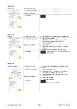
Page 22: ...ols begin to flash in sequence approximately 3 seconds In the first position the operation of the buttons of the related LEDs and of the groups of symbols shown on the LCD screen is checked turn the programme selector dial clockwise to run the diagnostic cycle for the operation of the various components and to read any alarms see diagnostic test During this phase if any key combination is pressed ...

Page 23: ... Purpose of the test To test operation of all the LEDs and switches Components activated The LEDs are turned on in sequence as are the symbol groups of the LCD display and its backlight Behaviour All LEDs turn on in sequence By pressing a key the corresponding icon unit lights up The code is shown on the LCD and a beep sounds All the icons on the LCD flash Working conditions There is a control to ...

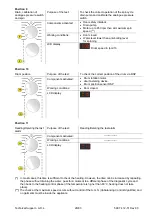
Page 24: ...imum time 5 mins LCD display Water level in the tub is displayed mm Position 4 Water fill to conditioner compartment Purpose of the test To check the correct operation of the conditioner compartment water route Components activated Door safety interlock Pre wash and wash solenoid valves Working conditions Door closed Water level below anti flooding level Maximum time 5 mins LCD display Water level...

Page 25: ...ng element Working conditions Door closed Water level high enough to cover the heating element Maximum time 10 mins or up to 90 C LCD display Temperature in C measured using the NTC probe Position 8 Leaks from the tub Purpose of the test To check for any water leaks from the tub during operation Components activated Door fastening device Wash solenoid if the water in the tub is not enough to cover...

Page 26: ...m via DSP Components activated Drum rotation motor door fastening device Drum position sensor DSP Working conditions Door closed LCD display Position 11 Reading Deleting the last alarm Purpose of the test Reading Deleting the last alarm Components activated Working conditions LCD display In most cases this time is sufficient to check the heating However the time can be increased by repeating the p...

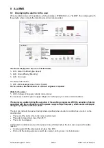
Page 27: ...s necessary to wait for power supply voltage and or frequency to restore normal conditions The alarms are enabled during the execution of the washing programme With the exception of alarms associated with the configuration and the power supply voltage frequency which are also displayed during the programme selection phase The door can normally be opened except where specified when an alarm conditi...

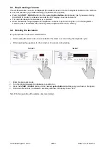
Page 28: ... the diagnostic mode Irrespective of the type of circuit board and configuration turn the programme selector knob clockwise to the tenth position and this will display the last alarm To display previous alarms press the button to the left of the START PAUSE button in sequence as shown in the figure To return to the last alarm press the START PAUSE button ...

Page 29: ...ppliance continues to perform the cycle or if in the programme selection phase it maintains the previously selected options stored in the memory 8 4 Deleting the last alarm It is good practice to cancel the alarms stored After reading the alarm codes to check whether the alarm re occurs during the diagnostic cycle After repairing the appliance to check whether it re occurs during testing Series 6 ...

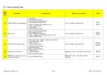
Page 30: ...w Water fill solenoid valve faulty Leaks clogging of pressure switch water circuit Pressure switch faulty Cycle is paused with door locked START RESET E21 Drain difficulty during washing Drain tube kinked clogged improperly positioned Drain filter clogged dirty Faulty wiring Pressure switch faulty Drain pump rotor blocked Drain pump faulty Main circuit board faulty Cycle is paused after 2 attempts...

Page 31: ... clogged dirty Drain pump faulty Leaks from pressure switch water circuit Pressure switch defective Wiring main circuit board Cycle paused START RESET E35 Overflow Water fill solenoid valve faulty Leaks from pressure switch water circuit Faulty wiring Pressure switch faulty Main circuit board faulty Cycle interrupted Safety drain cycle Drain pump continues to operate 5 min on then 5 min off etc RE...

Page 32: ...uit board faulty Safety drain cycle Cycle blocked RESET E44 Faulty sensing of door delay system Main circuit board faulty Safety drain cycle Cycle blocked RESET E45 Faulty sensing by door delay system triac Main circuit board faulty Safety drain cycle Cycle blocked RESET E51 Motor power triac short circuited Faulty wiring Motor faulty Main circuit board faulty After 5 attempts cycle blocked with d...

Page 33: ...ng element power relay faulty inconsistency between sensing and relay status Main circuit board faulty Safety water fill Cycle stops with door closed ON OFF RESET E68 Earth leakage Earth leakage between heating element and earth The heating phase is skipped START RESET E69 Heating element interrupted Faulty wiring Heating element for washing interrupted thermal fuse open Main circuit board faulty ...

Page 34: ...faulty The heating phase is skipped START RESET E74 NTC probe for wash cycle improperly positioned Faulty wiring NTC probe for wash cycle improperly positioned NTC probe faulty Main circuit board faulty The heating phase is skipped RESET E83 Error in reading selector Main circuit board faulty Incorrect configuration data Cycle cancelled START RESET E86 Selector configuration error Incorrect config...

Page 35: ...figuration Main circuit board faulty Incorrect configuration data Cycle blocked RESET E9C Display board configuration error Display board faulty START ON OFF RESET E9F Communication error between main board and display board Faulty wiring Display board faulty Main board faulty ON OFF EA1 No drum position signal made DSP sensor faulty Transmission belt broken Main circuit board faulty Faulty wiring...

Page 36: ...nal spin phases skipped START RESET EF6 Reset If it continues replace the main board EH1 Power supply frequency of appliance outside the limits Problem with the power supply network incorrect disturbed Main circuit board faulty Wait for nominal frequency conditions ON OFF EH2 Supply voltage too high Problem with the power supply network incorrect disturbed Main circuit board faulty Wait for nomina...

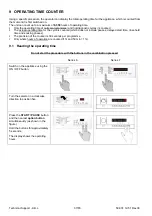
Page 37: ...s counted which does not include pauses delayed start time rinse hold time and soaking phases The precision of the counter is 30 seconds per programme Only whole hours of operation are counted 1hr and 59 min 1hr 9 1 Reading the operating time Do not start the procedure with the buttons in the combination pressed Series 6 Series 7 Switch on the appliance using the ON OFF button Turn the selector in...

Page 38: ...rating time is 6 550 hours the display will show the following sequence Phase 1 Phase 2 Phase 3 For two seconds It displays Hr For two seconds the following digits are displayed ª thousands 6 ª hundreds 5 For the next two seconds the following digits are displayed ª tens 5 ª units 0 At the end of phase three after the tens and units are displayed the cycle is repeated To return to normal mode eith...

Page 39: ... stains compartment to introduce the special stain removal product This option cannot be selected for WOOL and HAND WASH cycles 9 3 5 Super rinse Adds two rinses to the COTTON cycle one to the SYNTHETIC FABRICS DELICATES cycles Eliminates the spin at the end of washing 9 3 6 No spin It eliminates all the spin phases It adds three rinses to the COTTON CYCLE and one to the SYNTHETIC FABRICS cycle 9 ...

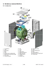
Page 40: ...ight and Left counterweights 7 Washing unit suspension springs 8 Drain pump 9 Pressure chamber 10 Lids 11 Drum 12 Inlet 13 Upper cover 14 Detergent dispenser 15 Water dispenser 16 Solenoid valves 17 Air Break 18 Washing unit 19 Transmission belt 20 Pulley 21 Drum rotation motor 22 DSP 23 Heating element 24 Main electronic circuit board 25 Control panel ...

Page 41: ... tub the cold water passes through the detergent dispenser picking up the detergent inside it This dispenser is split into 3 compartments marked with the symbols Wash dispenser 1 Pre wash dispenser 3 Fabric conditioner dispenser 2 1 Detergent dispenser 2 Fabric softener dispenser 3 Pre wash detergent dispenser 1 3 2 1 2 3 ...

Page 42: ...wash Wash During the washing phase the left solenoid valve is activated the water coming from the load pipe passes through the pressure reducer and then to the water dispenser which then sends the water into the right dispenser picking up the detergent needed for washing Fabric softener In some programmes the fabric softener in the central dispenser is picked up In order to do this both solenoid v...

Page 43: ...and held by a support 1 The washing unit is held suspended by two spiral springs 7 fitted to the back panel the swinging is muffled by two shock absorbers 8 one to the front and one at the back of the tub and fitted to the base frame The drum inserted in the washing unit is made up of 2 flanges 9 clamped to a perforated cylinder 14 with an open part inlet and in correspondence with the inlet there...

Page 44: ...44 83 599 74 12 51 Rev 00 10 4 Water circuit 10 4 1 OKO version drain circuit 1 Pre filing pipe 2 Drain pump 3 Drain pipe 4 Filter unit tub pipe containing the sphere 5 Pressure chamber 6 Filter unit amassed in the base frame ...

Page 45: ...ch powers all the electrical components cold and hot water solenoid valve where featured motor control board Inverter drain pump circulation pump where featured heating element door safety interlock drum light It controls the level of water via the analogue pressure switch It controls the state of the door It controls the speed of the motor It controls the temperature of the washing water via the ...

Page 46: ... Support A D L 46 83 599 74 12 51 Rev 00 10 5 1 Connecting electric parts Display board Series 7 Series 6 Analogue pressure DSP Motor Solenoid valve Drain pump Water control sensor Door lock Heating element NTC ...

Page 47: ... appliance and avoids the emission of radio frequency disturbance in the electricity mains It is incorporated into the main board 1 Main circuit board 11 2 Display board The main circuit board 1 supplies the power supply voltage to the control display board 12 Turn the selector dial to select the programmes press the buttons to choose the options and press the START PAUSE button to start or pause ...

Page 48: ... the foreign body is released The flow rate of these pumps is approximately 18 20 l min and the maximum head is 90 cm above ground level Fitted with overload cut out Synchronous pumps when powered on empty disconnected from the water circuit may not start in some cases because their very construction makes them need an antagonist torque on the wheel to allow the rotor to move in one of the two dir...

Page 49: ...itch which powers the drain pump When it is triggered the LCD display shows an ALARM if the machine is on See table of alarms 11 5 Heating element When replacing the heating element please refer to the code shown in the list of spare parts relating to the appliance It is strictly forbidden to tamper with the heating element in any way e g changing the NTC probe etc 1 NTC probe 2 Heating element Th...

Page 50: ...c casing An NTC type probe is used to control the washing temperature it is built in such a way that its internal resistance decreases as the temperature rises This drop in resistance is detected by the electronic control which when the desired temperature is reached disconnects the heating element The temperature of the water is controlled by the circuit board by means of an NTC probe incorporate...

Page 51: ... the pressure chamber When water is introduced into the tub this creates a pressure inside the hydraulic circuit that causes the membrane to change position This in turn modifies the position of the core inside the coil thus changing the inductance and the frequency of the oscillating circuit The PCB recognises how much water has been introduced into the tub according to the frequency 1 Main circu...

Page 52: ...n only be opened after a set time 1 Bimetallic PTC 2 Lock lever After pressing the START PAUSE key a pre established current passes through the bimetallic PTC 1 which becoming misshapen causes the lock lever 2 to move stopping the nib lock runner from moving At the end of the programme when the power supply to the bimetallic PTC 1 is disconnected a certain amount of time is needed to allow it prev...

Page 53: ...Technical Support A D L 53 83 599 74 12 51 Rev 00 11 9 Universal motor 1 Main circuit board 2 Door safety interlock 7 Tachometric generator 8 Motor ...

Page 54: ...otor voltage sensor integrated into the main board that allows us to have an electric power estimate Then via the motor s efficiency deducted from a motor load table we can obtain the mechanical power and lastly the torque signal Low speed Laundry arrangement High speed Spin phase The AGS control is carried out before each spin and it aims to achieve the following Measure the inertia moment Measur...

Page 55: ...mly across the surfaces of the drum Once this phase is complete we have the ideal condition for starting the spin firstly however before moving on to the maximum spin speed required by the kind of pre selected programme we still have one small phase where the unbalancing is once again checked Success condition for the start of the spin Arrangement of laundry Spin speed Drum speed Laundry Unravelin...

Page 56: ... manually 1 Main electronic circuit board 10 DSP internal circuit R1 1 KΩ 5 C1 4 7 µF 50 V 10 11 10 1 DPS operating control Power the DPS circuit between the points 5 V and Mass GND with a voltage of 5 V Position a 4 7 KΩ element between the OUT points and the mass GND Use the voltmeter to measure the voltage in the element ends V V points Test circuit DPS sensor with metallic mass inserted Voltag...

Page 57: ...3 Filter 4 Flow reducer 5 Coil 6 Spring 7 Moving core 8 Rubber 9 Membrane 10 Water outlet 11 11 1 Operating principle When idle the core pushed by a spring keeps the central hole of the membrane closed and so the latter hermetically seals access to the water inlet duct When the coil is powered the core is attracted releasing the central hole of the membrane Consequently the valve opens 1 Main circ...

Page 58: ... system which continuously monitors the flow sensor starts the drain pump and simultaneously displays an ALARM Low water pressure If the flow sensor does not generate a signal during the water fill phases even though power is being supplied to the solenoid valve the cause of this condition may be a closed water tap or clogged filter on the solenoid valve with ensuing low water pressure If this occ...

Page 59: ...Technical Support A D L 59 83 599 74 12 51 Rev 00 12 DIAGRAMS 12 1 WM diagram with UNIVERSAL MOTOR EWM ...

Page 60: ... 6 Wash solenoid 7 Tachometric generator motor 8 Motor 9 Heating element 10 DSP 11 Display board 12 Aqua control sensor 13 Drain pump DRAIN_YTY Drain pump triac DOOR_TY Door interlock triac PWELT_TY Pre wash solenoid triac WELV_TY Wash solenoid triac MOTOR_TY Drum rotation motor triac K1 Heating element relay K2 Heating element relay K3 Clockwise drum rotation motor K4 Anti clockwise drum rotation...

Page 61: ... a screwdriver into the side slits as shown in the figure Taking care not to ruin the paint work lever downwards in order to slightly widen the control panel until you unfasten the clips that hold it on Lift it up gently and move it towards the back 13 1 2 Assembly Introduce the runner pivots located on the control panel into the rails found on the sides of the washing machine Rotate it forwards P...

Page 62: ...h that hold the cover on the board 13 3 Key spring and light diffuser Once the board has been removed we can reach the key spring and led light diffusers Remove the key spring and led light diffuser releasing them from the clips that lock them on 13 4 Programme selector knob Before refitting the board we recommend you remove the knob to make it easier to insert the pivot With the aid of a screwdri...

Page 63: ...6 Water dispenser Remove the detergent dispenser Remove the control panel Open the two clamps using a screwdriver that block the pipes carrying water from the solenoid valves to the water dispenser Disconnect the pipes that carry the water from the solenoid valves to the water dispenser and the small service pipe if relevant Release the water dispenser and remove it ...

Page 64: ...of the washing machine in order to release them from the upper rails shown in the figure 13 8 Electronic pressure switch Remove the left side panel Release the pipe that connects the pressure chamber to the pressure switch Use a screwdriver to release the pressure switch fastening clips and remove it When replacing anything please refer to the code shown in the list of spare parts relating to the ...

Page 65: ...ser Disconnect the pipes that carry water from the solenoid valves to the water dispenser Press the stop tabs with a screwdriver Rotate the whole solenoid valve unit until it has been disconnected 13 10 Air break With the help of a screwdriver loosen the clamp locking the air break inlet pipe in position and remove the pipe Repeat the operation on the outlet pipe Release the pipe fastening clamp f...

Page 66: ...located on the frames to make it easier to remove the board Gently lift the whole board unit in order to release it and remove it Unfasten the clips using a screwdriver and open the connector protection cover Disconnect all the connectors and remove the board When replacing the board please refer to the code shown in the list of spare parts relating to the appliance When reinserting the connector ...

Page 67: ...ece to the base frame Remove the two internal screws that hold the frontal piece to the base frame Gently lift the inlet and remove the frontal piece 13 13 Door Lock Open the laundry loading cover Remove the side panels Remove the frontal piece Release the wiring from the cable tray Remove the door lock fastening screws Move leftwards towards the door lock unit until it has been fully released Dis...

Page 68: ...ver with the screwdriver and simultaneously rotate the base board downwards Repeat this operation on all three points In order to refit the base board Insert the base and rotate the base board in order to fully insert the three fastening clips 13 15 Transport roll Remove the right side Slightly tilt the washing machine to the left Release the transport roll using the screwdriver and remove it by p...

Page 69: ...16 Bellow seal Remove the left and right sides Remove the support wiring Cut the upper and lower cutting ring with a pair of pliers Remove the bellow taking care not to ruin the 2 bases Grease the bellow again in the fastening area to make assembly easier ...

Page 70: ...2 51 Rev 00 Start re assembling the bellow by inserting the lower part first Then insert the upper part Check that the bellow is inserted properly by checking that the reference notches are positioned properly External right and left sides ...

Page 71: ...Technical Support A D L 71 83 599 74 12 51 Rev 00 Inside frontal zone Insert the blocking rings Tighten them initially with your hands then block them with the aid of a pair of pliers ...

Page 72: ... dispenser Remove the electronic pressure switch In the models with an air break remove the pipe that connects it to the solenoid valves and the fastening clamp that holds the pipe to the outlet Lift it up in order to release the air break unit with the output pipe connected Remove the solenoid valve unit Before removing the front springs place a support under the motor to make the operation easie...

Page 73: ...ight screws and the 2 left screws that fasten the outlet to the column and back panel Unscrew the 2 back screws Gently lift the outlet from the back part Push it towards the back panel to free the front part held to the base by the fasteners Disconnect the door lock ...

Page 74: ...erted Place the counterweight and screw in the screws before the silicone has solidified 13 18 2 Left counterweight The left counterweight weighs around 13 kg so take care when removing it Dismantling Remove the left side panel If there is a spray pipe slacken the clamp and remove it If there is an aluminium frame remove the 2 screws that hold the counterweight to it Remove the 4 screws that hold ...

Page 75: ... 75 83 599 74 12 51 Rev 00 13 19 Shock absorbers Remove the left and right sides Front shock absorber Rear shock absorber Release the brass stop plugs positioned above and under each shock absorber Remove the shock absorbers ...

Page 76: ...ral screws that hold the pulley Extract the pulley by pulling it outwards When refitting the pulley make sure that the notch on the pulley coincides with the part with no cogs on the drum axis 13 21 Drum position sensor DSP Remove the right side panel before removing the belt check and make note of the belt s position on the motor axis Remove the pulley Unscrew the 2 screws that hold the DSP ...

Page 77: ...act the heating element by pulling it outwards 13 23 Drum rotation motor Remove the left and right panels Remove the belt Disconnect the mass connection and the motor power connector Unscrew the screws that hold the motor Remove the motor by extracting it from the left side of the equipment 13 24 Water control sensor Remove the left side panel Lie the equipment on its right side Remove the two sen...

Page 78: ... lid Remove the left side panel Lie the equipment on its right side Remove the 6 screws Remove the bottom lid Before refitting the bottom lid clean the slot runner well on the bottom of the washing machine and the slot base of the lid and fill it will silicone in order to make it fully seal proof again ...

Page 79: ...e the circulation pump is also inserted Disconnect the pump connectors Open the clamp that holds the pipe onto the pump outlet and remove it Use a screwdriver to lower the clips that hold the pump Move the pump towards the back of the machine and remove it 13 25 3 Circulation pump The circulation pump is inserted in a specific duct where the drain pump is also fastened and it held in place by two ...

Page 80: ...crew the bearing support paying attention to the threading direction and remove it Pay attention to the threading direction Right side pulley side unscrew in a clockwise direction Left side unscrew in an anti clockwise direction 13 26 1 Bearing support unit with seal ring Pay attention to the correct position of the seal ring during assembly Clean the axis and slightly grease the seal ring before ...

Page 81: ...pport unit with no seal ring Clean the axis and slightly grease the seal Insert the seal making sure that the thin lip seal is positioned outwards Push the seal as far as it can go The bearing unit is self locking so do not tighten it excessively Bearing support Bearing ...

Page 82: ...de off the belt and remove the pulley Remove the DSP drum positioning device Remove the two left and right counterweights Remove the heating element Remove the drum rotating motor Slacken the pipe tightening clamp in the flexible pipe and remove it Disconnect the pressure switch and release the pipe on its entire route Release the shock absorber pivots from the washing unit side Release all the wa...

Page 83: ...Technical Support A D L 83 83 599 74 12 51 Rev 00 Revisions Revision Date Description Written by Approved by on 00 03 2011 Document creation A D L A D L 03 2011 ...

Reviews: