STEP 3: Installation of Power Unit
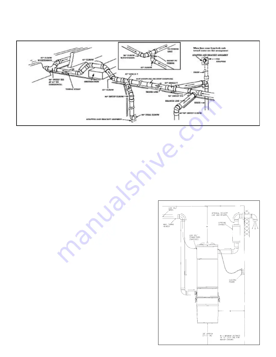
The power unit is screwed to the wall with the
bottom screws of the mounting bracket located
48" (1.2m) up from the floor to allow convenient
removal of the dirt canister. For proper motor
cooling, there must be at least 12" (30.5cm)
between the unit and the ceiling.
If mounting on plaster or panel walls, be sure
mounting bolts enter studs.
If mounting on concrete wall, drill the wall with a
masonry bit and insert plastic or lead anchors.
As an alternate mounting on concrete walls, 2"
x 4" (5.1 x 10.16cm) studs or plywood may be
suspended from overhead.
With the power unit mounted, strip the low-volt-
age wire and crimp into the two “slip-on” termi-
nals provided. Connect main tube line to left
side of power unit, with connector and clamp
provided. Do not cement this connection to the
power unit in case you wish to remove at some
future date. Do not install power unit where the
ambient temperature exceeds 120 degrees
Fahrenheit (48.9 degrees C).
NOTE: For top-loading units, follow directions
provided with unit.
This unit may be exhausted to exterior to expel
fumes, germs, and some noise. Use the same
tubing and fittings as before. If vented, the
exhaust air should not be vented into a wall,
ceiling, or concealed
space of a building. Venting over 10 ft. (3m) is
not recommended.
NOTE
: On/Off switch on power unit is for the
inlet on power unit only. All other inlets operate
automatically when the hose end is inserted into
the inlet valve or when the switch, which is
located on the hose handle, is turned on.
WIRING
Check local codes but use not less than #14-3
wire. Plug power unit cord into appropriate
120/220/230/ 240V - 50/60 cycle electrical out-
let. Be sure line voltage is sufficient to handle a
15 amp. load.


