background image

WARNING

: ELECTRIC SHOCK COULD OCCUR IF USED ON WET SURFACES.

GROUNDING INSTRUCTIONS

This appliance must be grounded. If it should malfunction or breakdown, grounding provides a path of least
resistance for electric current to reduce the risk of electric shock. This appliance is equipped with a cord hav-
ing an equipment grounding conductor and grounding plug. The plug must be plugged into an appropriate
outlet that is properly installed and grounded in accordance with all local codes and ordinances.

WARNING

Improper connection of the equipment-grounding conductor can result in a risk of electric shock. Check with
a qualified electrician or service person if you are in doubt as to whether
the outlet is properly grounded. Do not modify the plug provided with the
appliance—if it will not fit the outlet, have a proper outlet installed by a
qualified electrician. 

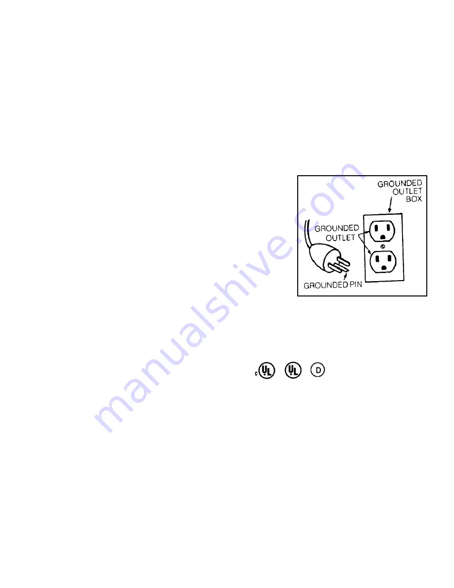
This appliance is for use on a nominal 120-volt circuit and has a ground
plug that looks like the plug illustrated in figure 21 for North American
units. For 220/230/240 volt units, consult your local building code/electri-
cian. 

Make sure that the appliance is connected to an outlet having the same
configuration as the plug. No adapter should be used with this appliance. 

Check power unit On/Off switch and all inlet valves for operation. This
power unit is intended for household and commercial use.

Important Safety Instructions

When using electrical appliances, basic safety precautions should always be followed, including the following: 

Read all instructions before using this vacuum. 

NOTE: Your Central Cleaning System is U.L. listed and C.U.L. listed for dry pick-up only. To reduce the risk of
electric shock,DO NOT USE outdoors or on wet surfaces.

DANGER

Always unplug power unit from the electrical outlet before servicing and cleaning.

WARNING

— 

To reduce the risk of burns, fire, electric shock, or injury to persons:

1. Keep cord away from heated surfaces.
2. Do not allow to be used as a toy. Close supervision is necessary when this vacuum is used by or near

children.

Summary of Contents for Afuera

Page 1: ...Do It Yourself Planning Installation Manual for your new AFUERATM Central Cleaning System ...

Page 2: ...d than wall valves and sometimes are the only practical installation They have some dis advantages as the hose must be inserted at the floor level rather than at a more convenient wall height Wall height is a matter of individual preference Some homeowners prefer the inlet at a convenient fingertip height about 30 inches 76cm while oth ers want it to match the electric outlet height STEP 2 Choose ...

Page 3: ...imum stud width for sufficient clearance for inner wall mounting bracket assembly is 2 3 4 7cm See Fig 3 above b Using METAL Stud Mounting Bracket Centered at the desired height above floor level cut an almost square opening 2 3 4 7cm wide by 2 1 2 6 35cm high in the wall directly above the 2 1 4 5 7cm sole plate hole Cut or file two 3 4 1 9cm high triangular pieces above and below the almost squa...

Page 4: ... of tubing joined by couplings may be required due to overhead space restric tions Precut these pieces and work quickly to prevent the cement on the end of the tubing from drying before it reaches the fitting at the valve below c Using PLASTIC Stud Mounting Bracket Having determined the location is suitable cut a 2 1 2 6 35cm x 4 3 8 11cm hole in the wall at the desired inlet valve loca tion See F...

Page 5: ...ce restric tions Precut these pieces and work quickly to prevent the on the end of the tubing from drying before it reaches the fitting at the valve below d Floor Valves To install a floor inlet drill a pilot hole with a coat hanger and check the location as previously described When you are sure that the pro posed location will not be blocked by a joist or other obstruction cut a hole in the carp...

Page 6: ...e metal bracket Attach wires to low voltage terminals at rear of inlet valve Place inner wall assembly lengthwise through wall opening and arrange assembly so that metal bracket is flush with inside surface of wall Screw inlet to wall as described previous ly in STEP 1 then complete as per Fig 16 f Wall Valve Installation New Construction Select a probable location for inlet valve and drill a pilo...

Page 7: ...ing or low voltage wire to pass PVC tubing through to hold it in position while you work Push a length of PVC tubing up into bottom of inlet valve assembly Bear in mind tube enters all fittings approximately 3 4 1 9cm Measure cut and slip fit this vertical line to main horizon tal line with a 90 degree sweep elbow To avoid potential clogging problems when installing tubing and fittings here are so...

Page 8: ... provided Do not cement this connection to the power unit in case you wish to remove at some future date Do not install power unit where the ambient temperature exceeds 120 degrees Fahrenheit 48 9 degrees C NOTE For top loading units follow directions provided with unit This unit may be exhausted to exterior to expel fumes germs and some noise Use the same tubing and fittings as before If vented t...

Page 9: ...circuit and has a ground plug that looks like the plug illustrated in figure 21 for North American units For 220 230 240 volt units consult your local building code electri cian Make sure that the appliance is connected to an outlet having the same configuration as the plug No adapter should be used with this appliance Check power unit On Off switch and all inlet valves for operation This power un...

Page 10: ...air face fingers and loose clothing away from any openings 9 Do not pick up cigarettes live hot ashes matches or similar materials 10 Never operate vacuum without dust bag and or filter in place 11 To disconnect turn all controls to the OFF position then remove plug from outlet 12 Never handle plug cord or power unit with wet hands 13 Electric shock could occur if used on wet surfaces 14 Use extra...

Reviews: