background image

SOI  02.10  FV 

127/142 

599 70 59-01 

3.5 -


REMOVING THE WATER FILLER DRAWER AND CONTROL  

 COMPONENTS 

 
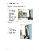
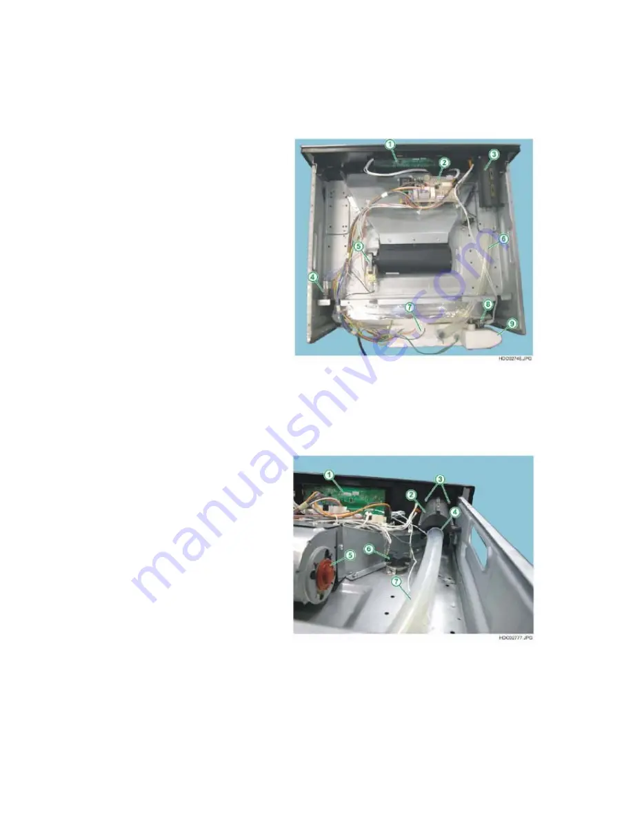
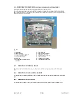
To remove the water filler drawer assembly: 
 
1 - Remove the top oven cover panel. 


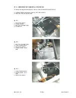
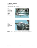
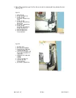
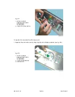
 Fig. 

263 


     1 - CONTROL UNIT - KRONOS 
     2 -  POWER BOARD OVC1000  
     3 -  WATER FILLER DRAWER  
     4 -  STEAM GENERATOR  
   

CONTROL RELAY  

     5 - TANGENTIAL COOLING FAN  
     6 -  WATER FILL PIPE  
     7 -  WATER TANK  
     8 - TEMPERATURE SENSOR 
      9 - EXPANSION CHAMBER 


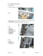
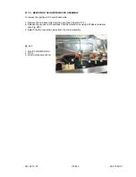
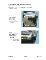
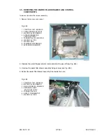
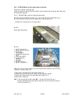
2 - Release the water fill pipe retainer clamp and slide the pipe off (see Fig. 264). 
 
3 - Unscrew the water filler drawer assembly fixing screws (see Fig. 264). 
 
4 - Extract the water filler drawer assembly from inside the oven. 


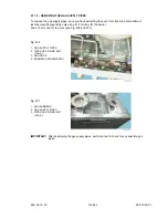
 Fig. 

264 


     1 - CONTROL UNIT - KRONOS 
     2 -  WATER FILLER DRAWER  
     3 - FIXING SCREWS - DRAWER  
     4 -  RETAINER CLAMP 
   

- WATER FILL PIPE 

     5 -  TANGENTIAL FAN  
     6 -  SAFETY THERMOSTAT  
     7 -  WATER FILL PIPE  


Summary of Contents for Built-in ovens

Page 1: ...ERVICE MANUAL COOKING ELECTROLUX HOME PRODUCTS Corso Lino Zanussi 30 Publication number I 33080 PORCIA PN ITALY 599 70 59 01 Fax 39 0434 394096 SOI Edition 02 2010 Rev 02 IT SERVICE FV Built in ovens ACCESS TO THE ACCESS PLUS STRUCTURE ...

Page 2: ...SOI 02 10 FV 2 142 599 70 59 01 ...

Page 3: ...OVING THE SPIT MOTOR page 31 2 4 8 REMOVING THE CONVECTION FAN MOTOR WITH SCREWS page 32 2 4 9 REMOVING THE CONVECTION FAN MOTOR WITH SNAP ON JOINT page 32 2 4 10 REMOVING THE CONVECTION FAN BLADE page 35 2 4 11 ACCESS TO THE FAN BLADE AND THE CONVECTION HEATING ELEMENT page 35 2 4 12 REMOVING THE LAMPHOLDER page 36 2 4 13 REMOVING THE DOOR LOCK ON PYROLYTIC MODELS page 37 2 4 13 1 METEOR DOOR LOC...

Page 4: ...GLASS PYRO DOOR EXTERNAL GLASS page 75 2 9 2 REMOVING THE METAL GLASS PYRO DOOR INTERNAL GLASS page 77 2 9 3 REMOVING THE METAL GLASS PYRO OVEN DOOR HANDLE page 80 2 9 4 REMOVING THE METAL GLASS PYRO OVEN DOOR HINGES page 80 2 10 REMOVING THE PLASTIC OVEN DOOR page 81 2 10 1 REMOVING THE PLASTIC OVEN DOOR INTERNAL GLASS page 83 2 10 2 REMOVING THE PLASTIC OVEN DOOR HANDLE page 85 2 10 3 REMOVING T...

Page 5: ...19 3 2 REMOVING THE REED LEVEL INDICATOR SWITCHES page 122 3 3 REPOSITIONING THE REED LEVEL INDICATOR SWITCHES page 124 3 4 REMOVING THE WATER TANK page 125 3 5 REMOVING THE WATER FILLER DRAWER AND CONTROL COMPONENTS page 127 3 6 WATER DRAIN VALVE page 129 3 7 ACCESSING THE TEMPERATURE SENSOR IN ELECTRONIC MODELS page 132 3 8 ACCESSING THE CONVECTION FAN page 133 4 ELECTRONIC GAS OVENS page 136 4 ...

Page 6: ...cess to certain components is possible by pulling the oven partially out of the compartment With the oven partially pulled out the service engineer can access the components in the front panel and electronic control unit for access to the other components located in the rear section it is necessary to remove the built in oven completely from its compartment To remove the oven 1 Remove the 4 screws...

Page 7: ... turning the main switch on the domestic circuit if featured to OFF 2 3 REMOVING THE CONTROL PANEL 2 3 1 REMOVING THE BEARING CONTROL PANEL In order to remove the control panel front panel firstly remove the knobs and knob caps where featured 1 Remove the upper panel see chapter 2 6 2 on page 41 2 Slide the knobs off the control components Fig 4 Remove the control component knobs Fig 5 1 FIXING SC...

Page 8: ...ol components 4 Slide the indicator lights out of the front panel towards the inside Fig 6 1 FIXING SCREWS FOR COMPONENT 2 BEARING FRONT PANEL 5 Remove the two rear screws which secure the front panel in place see Fig 7 Fig 7 1 FIXING SCREW FOR FRONT PANEL ONE ON EACH SIDE ...

Page 9: ...59 01 2 3 2 REMOVING THE CONTROL PANEL WITH PANEL SUPPORT NORMAL STYLING Fig 8 Example of styling with glass front panel 2 3 2 1 REMOVING THE GLASS FRONT PANEL To remove the glass front panel 1 Slide off the control knobs Fig 9 ...

Page 10: ...SOI 02 10 FV 10 142 599 70 59 01 2 Slide off the programmer buttons Fig 10 3 Cut the double sided adhesive tape on the front panel at the top using a knife see Fig 11 Fig 11 ...

Page 11: ...59 01 4 Detach the front panel at the top see Fig 12 Fig 12 1 PANEL SUPPORT 2 GLASS FRONT PANEL 5 Cut the double sided adhesive tape on the front panel at the bottom using a knife see Fig 13 Fig 13 6 Remove the glass front panel ...

Page 12: ...abs with a screwdriver and extract the programmer from the front side see Fig 14 Fig 14 1 CONTROL PANEL SUPPORT 2 FIXING TAB 3 ELECTRONIC PROGRAMMER 4 PHILIPS SCREWDRIVER 2 3 2 3 REMOVING THE INDICATOR LIGHTS To remove the indicator lights after removing the upper panel slide them out from the internal part of the oven see Fig 15 Fig 15 1 INDICATOR LIGHT 2 CONTROL PANEL SUPPORT 3 ELECTRONIC PROGRA...

Page 13: ...ue from the control panel support using a cloth use some solvent if necessary see Fig 16 and 17 Fig 16 1 OLD DOUBLE SIDED TAPE RESIDUE Fig 17 2 If the old glass front panel is being repositioned you will need to wipe off any double sided adhesive tape residue that may have built up on the internal side of the front panel see Fig 18 Fig 18 1 OLD DOUBLE SIDED TAPE RESIDUE ...

Page 14: ...e sided adhesive tape part no 358199008 6 onto the top of the front panel support see Fig 19 Fig 19 1 DOUBLE SIDED ADHESIVE TAPE PART NO 358199008 6 2 PANEL SUPPORT 4 Cut a 50 cm long piece of double sided adhesive tape see Fig 20 and 21 Fig 20 Fig 21 ...

Page 15: ...pport see Fig 23 Fig 23 7 Glue the front panel to the control panel support making sure you position it correctly so that the side edges of the front panel coincide with the control panel support see Fig 24 Fig 24 NOTE In the models with knobs and buttons to facilitate the correct positioning of the positioning of the front panel it is possible to insert some of the knobs and buttons and these can...

Page 16: ...9 70 59 01 Fig 25 8 Once you have glued the front panel you need to exert some pressure with your hands evenly at the top and bottom of the front panel in order to facilitate perfect adherence see Fig 26 and 27 Fig 26 Fig 27 ...

Page 17: ...SOI 02 10 FV 17 142 599 70 59 01 9 Replace the control knobs and the programmer buttons Fig 28 Fig 29 ...

Page 18: ...e off the control knobs 3 Unscrew the component fixing screws from the front see Fig 30 and 31 Fig 30 1 FIXING SCREWS FOR THE ENERGY REGULATOR 2 PIN FOR THE KNOB Fig 31 1 CONTROL PANEL 2 FIXING SCREW FOR THE ENERGY REGULATOR 3 TORX SCREWDRIVER 4 Extract the component from the rear see Fig 32 Fig 32 1 ENERGY REGULATOR 2 PANEL SUPPORT FOR CONTROL PANEL ...

Page 19: ...see chapter 2 6 1 Remove the two screws which secure the control panel assembly in place see Fig 33 Fig 33 1 FIXING SCREW FOR FRONT PANEL ONE ON EACH SIDE Fig 34 1 CONTROL COMPONENTS 2 CONTROL COMPONENT SUPPORT N B From January 2010 serial number 001 access to the top of the oven has improved thanks to the progressive introduction of a new one piece top oven cover see chapter 2 6 1 ...

Page 20: ...02 10 FV 20 142 599 70 59 01 2 Slide off the control knobs by pulling them outwards Fig 35 1 POP IN POP OUT KNOB Fig 36 1 POP IN POP OUT KNOB 2 CONTROL COMPONENT SUPPORT 3 CONTROL COMPONENT ENERGY REGULATOR ...

Page 21: ...he washers off from the knob control pins in the models where featured Fig 38 1 PIN FOR THE COMPONENT KNOB 2 WASHER 5 Remove the screws of the control components switches energy regulators thermostat two for each component see Fig 39 that secure the component to the related support Fig 39 1 FIXING SCREWS FOR THE CONTROL COMPONENT 2 PIN FOR THE COMPONENT KNOB 3 TORX SCREWDRIVER ...

Page 22: ...op out knob support ferrules by turning them anti clockwise see Fig 40 and 41 Fig 40 1 SUPPORT COMPONENT FIXING FERRULE 2 CONTROL COMPONENT SUPPORT 3 CONTROL COMPONENT ENERGY REGULATOR Fig 41 7 Slide off the control component supports from the front Fig 42 ...

Page 23: ...ttons where featured Fig 43 1 PROGRAMMER BUTTONS 9 Remove the two programmer fixing screws where featured Fig 44 1 PROGRAMMER FIXING SCREWS 2 CONTROL PANEL 10 Extract the programmer assembly in the models where featured Fig 45 1 PROGRAMMER ASSEMBLY 2 CONTROL PANEL ...

Page 24: ... To replace the programmer it is necessary to release it from the related fixing bracket where it is slotted in place Fig 47 1 PROGRAMMER 2 PROGRAMMER SUPPORT BRACKET 11 Slide out the indicator lights from the front panel Follow the above steps in the reverse order to reposition them ...

Page 25: ...e following components are accessible the lampholder the various heating elements the convection fan motor and the terminal board with cable clamp 2 4 1 REAR VIEW OF NORMAL OVEN Fig 48 1 GRILL HEATING ELEMENT 2 TOP PANEL HEATING ELEMENT 3 LAMPHOLDER 4 COOLING FAN CONTROL THERMOSTAT 5 CONVECTION FAN 6 CONVECTION HEATING ELEMENT 7 EARTH CONNECTION 8 TERMINAL BOARD 9 CABLE CLAMP 10 BOTTOM HEATING ELE...

Page 26: ...Fig 49 1 LAMPHOLDER 2 ELECTRICAL CONTACTS OF GRILL TOP HEATING ELEMENT 3 DOOR LOCK SAFETY THERMOSTAT 4 TEMPERATURE SENSOR PT500 5 SENSOR CONNECTOR 6 TERMINAL BOARD 7 SPIT MOTOR 8 CONVECTION MOTOR 9 POWER SUPPLY CABLE 10 CABLE CLAMP 11 ELECTRICAL CONTACTS OF BOTTOM HEATING ELEMENT ...

Page 27: ...FAN 7 FACTORY TEST BUTTON SERVICE 8 PYROLYSIS MULTIPLE THERMOSTAT 9 LAMPHOLDER 10 FAN THERMOSTAT 11 PYROLYSIS THERMOSTAT SENSOR 12 DOOR LOCK SAFETY THERMOSTAT 13 OVEN THERMOSTAT SENSOR 14 ELECTRICAL CONTACTS OF GRILL TOP HEATING ELEMENT 15 ELECTRICAL CONTACTS OF CONVECTION HEATING ELEMENT 16 SPIT MOTOR 17 CONVECTION MOTOR 18 TERMINAL BOARD 19 ELECTRICAL CONTACTS OF BOTTOM HEATING ELEMENT ...

Page 28: ...itted into its housing To remove the terminal board use a screwdriver to pry open the anchor tab see Fig 51 and Fig 53 2 4 4 1 3 POLE TERMINAL BOARD Fig 51 1 TERMINAL BOARD 2 ANCHOR TAB Fig 52 1 TERMINAL BOARD 2 ELECTRICAL CONNECTIONS see Fig 55 3 EARTH CONNECTION 4 POWER SUPPLY CABLE 5 CABLE CLAMP 6 FIXING SCREWS FOR CABLE CLAMP ...

Page 29: ...142 599 70 59 01 2 4 4 2 5 POLE TERMINAL BOARD Fig 53 1 TERMINAL BOARD 2 ANCHOR TAB Fig 54 1 ELECTRICAL CONNECTIONS see Fig 55 2 TERMINAL BOARD 3 EARTH CONNECTION 2 4 4 3 ELECTRIC CONNECTIONS TO TERMINAL BOARDS Fig 55 ...

Page 30: ... Remove the two fixing screws from the rear internal part of the oven liner see Fig 56 Pos 3 keeping the nuts situated at the rear of the oven see Fig 57 Pos 2 Detach the connection cables situated at the rear of the oven see Fig 57 Pos 4 Slide the heating element out from the inside the oven Fig 56 1 TOP GRILL HEATING ELEMENT 2 UPPER FIXING SCREW FOR THE HEATING ELEMENT 3 REAR FIXING SCREWS FOR T...

Page 31: ...BLE CLAMP 10 BOTTOM HEATING ELEMENT 2 Unfasten the fixing screws from the rear Fig 59 1 BOTTOM HEATING ELEMENT 2 FIXING SCREWS FOR THE BOTTOM HEATING ELEMENT 3 ELECTRICAL CONNECTIONS FOR THE HEATING ELEMENT 3 Slide the heating element out from the rear 2 4 7 REMOVING THE SPIT MOTOR In order to remove the spit motor simply unscrew the two fixing screws see Fig 60 Pos 5 Fig 60 1 CONVECTION HEATING E...

Page 32: ...ing the fan in place Fig 60 Pos 7 2 4 9 REMOVING THE CONVECTION FAN MOTOR WITH SNAP ON JOINT To remove the convection fan with snap on joint 1 Push the motor anchor tab using a screwdriver see Fig 61 2 Turn the motor clockwise and extract it see Fig 62 and 63 Fig 61 1 CONVECTION FAN MOTOR 2 MOTOR SUPPORT BRACKET POSITIONED AT THE REAR OF THE OVEN 3 PHILIPS SCREWDRIVER 4 ANCHOR TAB Fig 62 1 MOTOR S...

Page 33: ...AR OF THE OVEN 2 CONVECTION FAN MOTOR To reposition the convection fan with snap on joint 1 Reposition the anchor tab correctly lifting it slightly with a Philips screwdriver see Fig 64 Fig 64 1 MOTOR SUPPORT BRACKET POSITIONED AT THE REAR OF THE OVEN 2 PHILIPS SCREWDRIVER 3 ANCHOR TAB ...

Page 34: ...tor tabs to the purpose built fixing apertures see Fig 65 Fig 65 1 MOTOR SUPPORT BRACKET POSITIONED AT THE REAR OF THE OVEN 2 CONVECTION FAN MOTOR 3 Turn the motor anti clockwise to secure it in place see Fig 66 Fig 66 1 MOTOR SUPPORT BRACKET POSITIONED AT THE REAR OF THE OVEN 2 CONVECTION FAN MOTOR ...

Page 35: ...L 2 OVEN BOTTOM PANEL 3 FIXING TABS FOR OVEN BOTTOM PANEL 4 SIDE GRIDS 2 4 11 ACCESS TO THE FAN BLADE AND THE CONVECTION HEATING ELEMENT Once the oven back panel has been removed the following components are accessible the convection fan and the circular convection heating element Fig 68 1 GRILL TOP HEATING ELEMENT 2 FIXING SCREW FOR THE GRILL TOP HEATING ELEMENT 3 LAMPHOLDER 4 CONVECTION FAN 5 FI...

Page 36: ... Remove the central fixing screw while holding the fan blade in place Caution The fixing screw thread is reversed anti clockwise tightening 2 4 12 REMOVING THE LAMPHOLDER To remove the lampholder once you have removed the rear panel 1 With a 3 mm tip screwdriver detach the connector wires Fig 69 1 LAMPHOLDER 2 CONNECTOR WIRES 3 3 mm SCREWDRIVER 2 Use a normal screwdriver to pry open the fixing tab...

Page 37: ...ven from its compartment just remove the upper panel and unscrew the two screws on the door lock assembly see Fig 71 and 72 2 4 13 1 METEOR DOOR LOCK Fig 71 1 METEOR TYPE DOOR LOCK 2 FIXING SCREWS FOR DOOR LOCK 3 TORX SCREWDRIVER 2 4 13 2 ELTEK DOOR LOCK Fig 72 1 ELTEK TYPE DOOR LOCK 2 CONNECTORS FOR CONNECTION 3 FIXING SCREWS ...

Page 38: ...L 2 5 1 REMOVING THE FRONT SEAL ON NORMAL OVENS To remove the front seal release the 4 fixing screws from the fixing hole pulling the seal outwards Fig 73 and 74 Fig 73 FIXING POINTS FOR FRONT SEAL Fig 74 1 FIXING HOLE FOR TAB 2 ANCHOR TAB FOR SEAL 3 FRONT SEAL ...

Page 39: ...hole front part towards the inside of the front see Fig 75 sliding them out of the holes by pulling them outwards FIXING POINTS FOR FRONT SEAL Fig 75 1 JOINING POINT OF SEAL To facilitate the operation it is advisable to start from the joining point of the seal see Fig 75 and 76 Fig 76 1 FIXING HOLE FOR SEAL 2 SEAL ANCHOR TAB 3 START OF FRONT SEAL 4 END OF FRONT SEAL ...

Page 40: ...m January 2010 serial no 001 a new one piece top oven cover will gradually be introduced FORMER OVEN COVER IN TWO PIECES NEW OVEN COVER IN ONE PIECE Fig 77 Fig 78 There will be different fixing points and access to components in the top section of the oven will change FORMER SYSTEM FIXING SCREWS Fig 79 1 FIXING SCREWS FRONT PANEL 2 FIXING SCREWS REAR PANEL Fig 80 1 TOP FRONT SCREWS 2 LEFT SIDE SCR...

Page 41: ... the electronic version the electronic boards Control Unit and power board and the control components 2 6 2 1 NORMAL ELECTROMECHANICAL VERSION 1 Unfasten the 3 fixing screws on the upper panel Fig 81 Upper panel fixing screws Fig 82 1 INDICATOR LIGHTS 2 OVEN THERMOSTAT 3 END OF COOKING PROGRAMMER 4 FUNCTION SELECTOR N B From January 2010 serial number 001 access to the top of the oven has improved...

Page 42: ...ng programmer indicator lights etc 1 Remove the control panel front panel see chapter 2 3 entitled REMOVING THE CONTROL PANEL 2 Detach the connection wires of the component marking their position 3 Remove the fixing screws of the component see chapter 2 3 entitled REMOVING THE CONTROL PANEL 4 Remove the component ...

Page 43: ...ctor end of cooking programmer indicator lights etc 1 Remove the control panel front panel see chapter 2 3 entitled REMOVING THE CONTROL PANEL 2 Detach the connection wires of the component marking their position 3 Remove the fixing screws of the component see chapter 2 3 entitled REMOVING THE CONTROL PANEL 4 Remove the component N B From January 2010 serial number 001 access to the top of the ove...

Page 44: ...e connection wires marking their position 2 Release the board from the plastic supports see Fig 87 for the OVC1000 version or remove the fixing screws for the OVC2000 version 3 Remove the board Fig 87 1 PLASTIC SUPPORT PINS FIXING THE BOARDS IN PLACE 2 OVC1000 POWER BOARD N B From January 2010 serial number 001 access to the top of the oven has improved thanks to the progressive introduction of a ...

Page 45: ...CTION SELECTOR 5 DOOR LOCK When removing an electronic board 1 Detach the connection wires marking their position 2 Release the board from the plastic supports see Fig 87 for the OVC1000 version or remove the fixing screws for the OVC2000 version 3 Remove the board N B From January 2010 serial number 001 access to the top of the oven has improved thanks to the progressive introduction of a new one...

Page 46: ...L depending on the styling 2 Detach the connection wires of the component marking their position 3 Remove the fixing screws of the component see chapter 2 4 entitled REMOVING THE CONTROL PANEL depending on the styling 4 Remove the component Fig 90 1 ENERGY REGULATORS FOR THE HOB 2 ELECTRONIC PROGRAMMER 3 INDICATOR LIGHTS 4 FUNCTION SELECTOR 5 OVEN THERMOSTAT 6 CONNECTION CONNECTOR FOR THE HOB N B ...

Page 47: ...es of the component marking their position 3 Remove the fixing screws of the component see chapter 2 4 entitled REMOVING THE CONTROL PANEL depending on the styling 4 Remove the component Fig 91 1 NORMAL ENERGY REGULATORS FOR THE HOB 2 DOUBLE ENERGY REGULATOR FOR THE HOB 3 OVEN FUNCTION SELECTOR 4 INDICATOR LIGHTS 5 RHEA ELECTRONIC PROGRAMMER 6 TEMPERATURE CONTROL POTENTIOMETER 7 DOOR LOCK FOR PYRO...

Page 48: ...NEL depending on the styling 2 Detach the Control Unit Power board connection connector see Fig 92 3 Slide the Control Unit off from the side to release it from the retainer hooks see Fig 93 Fig 92 1 CONTROL PANEL 2 AVANTGARDE CONTROL UNIT 3 CONTROL UNIT POWER BOARD CONNECTION CONNECTOR Fig 93 1 AVANTGARDE CONTROL UNIT N B From January 2010 serial number 001 access to the top of the oven has impro...

Page 49: ...NTROL PANEL depending on the styling 2 Detach the Control Unit Power board connection connector see Fig 94 3 Slide the Control Unit off from the side to release it from the retainer hooks see Fig 93 Fig 94 1 CONTROL PANEL 2 AVANTGARDE CONTROL UNIT 3 CONTROL UNIT POWER BOARD CONNECTION CONNECTOR 4 DOOR LOCK ASSEMBLY N B From January 2010 serial number 001 access to the top of the oven has improved ...

Page 50: ...t Bar board connection connector see Fig 95 5 Release the retainer hooks positioned in the lower part using a Philips screwdriver see Fig 96 Fig 95 1 CONTROL PANEL 2 LIGHT BAR CONNECTION CONNECTORS 3 TOUCH BOARD CONNECTION CONNECTORS 4 VISION CONTROL UNIT 5 CONNECTION CONNECTOR TO THE OVC2000 POWER BOARD 6 CONNECTION CONNECTORS TO TOUCH BOARD 7 CONNECTION CONNECTOR TO LIGHT BAR BOARD 8 LIGHT BAR P...

Page 51: ...97 4 Detach the Control Unit Light Bar board connection connector see Fig 97 5 Release the retainer hooks positioned in the lower part using a Philips screwdriver see Fig 96 Fig 97 1 CONTROL PANEL 2 LIGHT BAR CONNECTION CONNECTORS 3 TOUCH BOARD CONNECTION CONNECTORS 4 VISION CONTROL UNIT 5 CONNECTION CONNECTOR TO THE OVC2000 POWER BOARD 6 CONNECTION CONNECTORS TO TOUCH BOARD 7 CONNECTION CONNECTOR...

Page 52: ... FAN ON ELECTROMECHANICAL VERSION WITH HOB CONTROLS To remove one of the components 1 Unfasten the fixing screws on the upper panel 2 Detach the connection wires for the tangential cooling fan or thermostat 3 Unfasten the fixing screws on the fan or thermostat 4 Extract the component Fig 98 1 ENERGY REGULATORS 2 ELECTRONIC PROGRAMMER 3 INDICATOR LIGHTS 4 FUNCTION SELECTOR 5 OVEN THERMOSTAT 6 CONNE...

Page 53: ...SOI 02 10 FV 53 142 599 70 59 01 Fig 100 1 COOLING FAN N B When mounting the tangential fan assembly make sure you position the steam vent correctly see Fig 101 Fig 101 1 STEAM VENT 2 TANGENTIAL FAN ...

Page 54: ...fferent fixing system has gradually been introduced instead of the fan with the plastic body To remove the fan 1 Unfasten the fixing screws on the upper panel 2 Detach the connection wires for the tangential cooling fan 3 Unfasten the fan fixing screws see Fig 102 4 Extract the component Fig 102 1 FAN ELECTRICAL CONNECTIONS 2 COOLING FAN WITH METAL BODY 3 LEFT FIXING SCREW 4 RIGHT FIXING SCREWS ...

Page 55: ...tach the connection wires for the tangential cooling fan or thermostat 3 Unfasten the fixing screws on the fan or thermostat 4 Extract the component Fig 103 1 HOB HOTPLATE CONTROL 2 KRONOS CONTROL UNIT BOARD 3 POWER BOARD OVC1000 4 SAFETY THERMOSTAT 5 CONNECTOR FOR HOB CONNECTION 6 COOLING FAN Fig 104 1 FIXING SCREWS FOR COOLING FAN 2 FAN MOTOR 3 FAN BODY 4 ELECTRICAL CONTACTS FOR CONNECTION ...

Page 56: ...the tangential cooling fan or thermostat 3 Unfasten the fixing screws on the fan or thermostat 4 Extract the component Fig 105 1 TEMPERATURE CONTROL POTENTIOMETER 2 KRONOS CONTROL UNIT BOARD 3 FUNCTION SELECTOR 4 POWER BOARD OVC1000 5 DOOR LOCK 6 SAFETY THERMOSTAT 7 DROP RESISTOR 8 COOLING FAN MOTOR 9 FAN BODY Fig 106 1 FIXING SCREWS FOR COOLING FAN 2 FAN MOTOR 3 FAN BODY 4 ELECTRICAL CONTACTS FOR...

Page 57: ...g fan or thermostat 3 Unfasten the fixing screws on the fan or thermostat 4 Extract the component Fig 107 1 FUNCTION SELECTOR 2 TIMER 3 OVEN THERMOSTAT 4 THERMOSTAT INDICATOR LIGHT 5 DOOR LOCK ASSEMBLY 6 FACTORY TEST BUTTON SERVICE 7 DROP RESISTOR FOR FAN 8 PYROLYSIS SAFETY THERMOSTAT 9 COOLING FAN 10 PYROLYSIS MULTIPLE THERMOSTAT Fig 108 1 FIXING SCREWS FOR COOLING FAN 2 COOLING FAN MOTOR 3 FAN B...

Page 58: ... Unfasten the fixing screws on the fan or thermostat 4 Extract the component Fig 109 1 NORMAL ENERGY REGULATORS 2 DOUBLE ENERGY REGULATOR 3 FUNCTION SELECTOR 4 RHEA ELECTRONIC PROGRAMMER 5 TEMPERATURE CONTROL POTENTIOMETER 6 DOOR LOCK 7 DROP RESISTOR 8 FAN MOTOR 9 CONNECTOR FOR CONNECTION TO HOB 10 COOLING FAN 11 OVC1000 POWER BOARD Fig 110 1 FIXING SCREWS FOR COOLING FAN 2 COOLING FAN MOTOR 3 FAN...

Page 59: ...ing screws on the upper panel 2 Detach the connection wires for the tangential cooling fan 3 Unfasten the fixing screws on the fan 4 Extract the component Fig 111 1 AVANTGARDE CONTROL UNIT 2 TANGENTIAL FAN MOTOR 3 TANGENTIAL FAN 4 POWER BOARD OVC2000 Fig 112 1 FIXING SCREWS FOR COOLING FAN 2 COOLING FAN 3 COOLING FAN MOTOR 4 ELECTRICAL CONTACTS FOR CONNECTION ...

Page 60: ...upper panel 2 Detach the connection wires for the tangential cooling fan 3 Unfasten the fixing screws on the fan 4 Extract the component Fig 113 1 AVANTGARDE CONTROL UNIT 2 DROP RESISTOR FOR FAN 3 FAN MOTOR 4 TANGENTIAL FAN 5 DOOR LOCK ASSEMBLY 6 POWER BOARD OVC2000 Fig 114 1 FIXING SCREWS FOR COOLING FAN 2 COOLING FAN 3 COOLING FAN MOTOR 4 ELECTRICAL CONTACTS FOR CONNECTION ...

Page 61: ...ews on the upper panel 2 Detach the connection wires for the tangential cooling fan 3 Unfasten the fixing screws on the fan 4 Extract the component Fig 115 1 VISION CONTROL UNIT 2 LIGHT BAR POWER BOARD 3 FAN MOTOR 4 TANGENTIAL FAN 5 POWER BOARD OVC2000 Fig 116 1 FIXING SCREWS FOR COOLING FAN 2 COOLING FAN 3 COOLING FAN MOTOR 4 ELECTRICAL CONTACTS FOR CONNECTION ...

Page 62: ...ction wires for the tangential cooling fan 3 Unfasten the fixing screws on the fan 4 Extract the component Fig 117 1 VISION CONTROL UNIT 2 DOOR LOCK 3 SAFETY THERMOSTAT 4 LIGHT BAR POWER BOARD 5 DROP RESISTOR 6 TANGENTIAL FAN MOTOR 7 TANGENTIAL FAN 8 POWER BOARD OVC2000 Fig 118 1 FIXING SCREWS FOR COOLING FAN 2 TANGENTIAL COOLING FAN 3 TANGENTIAL COOLING FAN MOTOR 4 ELECTRICAL CONTACTS FOR CONNECT...

Page 63: ... the same as in the previous models To remove the oven door 1 Open the door completely 2 Raise the two hinge retainers see Fig 119 120 and 121 3 Slide the door off upwards Fig 119 1 FRONT SEAL 2 OVEN FRONT PANEL 3 DOOR INTERIOR INNER DOOR 4 OVEN HINGE 5 HINGE RETAINER HOOK Fig 120 1 HINGE RETAINER HOOK RAISED 2 OVEN HINGE ...

Page 64: ... REMOVING THE DOOR EXTERNAL GLASS NORMAL OVEN Once you have removed the oven door 1 Remove the two screws on the lower part of the inner door see Fig 122 Pos 5 2 Slide the glass off from the top of the door to release it from the metal fixing strip Fig 122 1 INNER DOOR 2 DOOR EXTERNAL GLASS 3 OVEN HINGE RIGHT 4 HINGE FIXING SCREW RIGHT 5 EXTERNAL GLASS FIXING SCREWS 6 HINGE FIXING SCREW LEFT 7 OVE...

Page 65: ...ET TO SECURE THE GLASS 2 LOWER RIGHT FIXING BRACKET TO SECURE THE GLASS 3 DOOR EXTERNAL GLASS 4 FIXING SCREWS FOR HANDLE 5 INNER DOOR FIXING BRACKET 2 7 3 REMOVING THE CENTRAL GLASS ON THE NORMAL TRIPLE GLASS OVEN DOOR Once you have removed the external glass from the door you can access the door internal glass Fig 124 1 DOOR CENTRAL GLASS 2 LEFT UPRIGHT ON CENTRAL GLASS 3 DOOR AIR GUIDE 4 RIGHT U...

Page 66: ...door remains the same as in the previous models To remove the oven door 1 Open the door completely 2 Raise the two hinge retainers see Fig 125 126 and 127 3 Slide the door off upwards Fig 125 1 FRONT SEAL 2 OVEN FRONT PANEL 3 DOOR INTERIOR 4 OVEN HINGE 5 HINGE RETAINER HOOK Fig 126 1 HINGE RETAINER HOOK RAISED 2 OVEN HINGE ...

Page 67: ...N B When repositioning the door before you close it make sure you raise the hooks completely to their original position see Fig 125 2 8 1 REMOVING THE UPPER END PIECES ON ALL GLASS DOOR Fig 128 1 OVEN HINGES 2 DOOR SIDE UPRIGHTS 3 INTERNAL GLASS 4 EXTERNAL GLASS 5 UPPER END PIECES 6 UPPER GRILLE ...

Page 68: ...ds see Fig 132 Fig 129 1 EXTERNAL DOOR GLASS 2 LEFT UPRIGHT 3 INTERNAL DOOR GLASS 4 PHILIPS SCREWDRIVER 5 FIXING SCREW LEFT END PIECE 6 LEFT END PIECE WITH DOOR LOCK RETAINER HOOK 7 RUBBER BUFFER 8 UPPER GRILLE Fig 130 1 LEFT END PIECE 2 RETAINER HOOK FOR DOOR LOCK Fig 131 1 INTERNAL DOOR GLASS 2 RIGHT UPRIGHT 3 EXTERNAL DOOR GLASS 4 UPPER GRILLE 5 RIGHT END PIECE 6 FIXING SCREW RIGHT END PIECE 7 ...

Page 69: ...ixing screws see Fig 133 Fig 133 1 UPPER LEFT END PIECE 2 UPPER GRILLE 3 UPPER RIGHT END PIECE 4 END PIECE SPRING CLIP 5 FIXING SCREWS FOR THE UPPER GRILLE N B Before repositioning the upper end pieces grille assembly in the door make sure the end piece spring clips are inserted correctly see Fig 134 Fig 134 1 END PIECE SPRING CLIP 2 UPPER END PIECE 3 UPPER GRILLE ...

Page 70: ...ying attention to the sequence of glass panes and to the position of the rubber buffer see Fig 135 Fig 135 1 OVEN DOOR HINGES 2 FIRST INTERNAL DOOR GLASS PANE 3 CENTRAL RUBBER BUFFER FOR INTERNAL GLASS 4 EXTERNAL DOOR GLASS Fig 136 1 OVEN DOOR HINGES 2 THIRD DOOR INTERNAL GLASS PANE 3 SECOND DOOR INTERNAL GLASS PANE 4 SIDE GLAZING RETAINER BUFFERS Fig 137 1 OVEN DOOR HINGES 2 THIRD DOOR INTERNAL G...

Page 71: ... RIGHT DOOR UPRIGHT 3 EXTERNAL GLASS PANE 2 8 3 REMOVING THE ALL GLASS PYRO OVEN DOOR HANDLE Once you have removed the internal glazing as explained in the previous chapters 1 Remove the two screws on the inside of the door see Fig 139 and 140 Fig 139 1 DOOR HINGES 2 INTERNAL GLASS SIDE RETAINER BUFFERS 3 FIXING SCREWS FOR HANDLE Fig 140 1 RIGHT DOOR UPRIGHT 2 INTERNAL GLASS SIDE RETAINER BUFFER 3...

Page 72: ...hinge cover assembly inside the side door uprights see Fig 141 and 142 2 Slide off the hinge hinge cover assembly see Fig 143 Fig 141 1 SIDE UPRIGHTS 2 LEFT OVEN HINGES 3 FIXING SCREWS FOR HINGES 4 FIXING SCREWS FOR HINGE COVERS Fig 142 1 OVEN HINGE 2 SIDE UPRIGHT 3 FIXING SCREWS FOR HINGE 4 FIXING SCREW FOR HINGE COVER 5 DOOR EXTERNAL GLASS Fig 143 1 DOOR EXTERNAL GLASS 2 SIDE UPRIGHT 3 OVEN HING...

Page 73: ...screwing the side screw and the front one see Fig 144 and 145 Fig 144 1 DOOR HINGE 2 SIDE FIXING SCREW FOR HINGE COVER 3 FRONT FIXING SCREW FOR HINGE COVER 4 HINGE COVER 5 TORX SCREWDRIVER Fig 145 1 DOOR HINGE 2 HINGE COVER 3 FRONT FIXING SCREW FOR HINGE COVER 4 TORX SCREWDRIVER ...

Page 74: ...ns the same as in the previous models To remove the oven door 1 Open the door completely 2 Raise the two hinge retainers see Fig 146 147 and 148 3 Slide the door off upwards Fig 146 1 FRONT SEAL 2 OVEN FRONT PANEL 3 DOOR INTERIOR INNER DOOR 4 OVEN HINGE 5 HINGE RETAINER FOR HINGE Fig 147 1 HINGE RETAINER FOR HINGE RAISED 2 OVEN HINGE ...

Page 75: ...ition see Fig 146 2 9 1 REMOVING THE METAL GLASS PYRO DOOR EXTERNAL GLASS Once you have removed the oven door 1 Remove the two screws on the lower part of the inner door see Fig 149 Pos 5 2 Slide the glass off from the top of the door to release it from the metal fixing supports Fig 149 1 OVEN DOOR HINGES 2 DOOR INTERNAL GLASS 3 INNER DOOR 4 HINGE FIXING SCREWS 5 EXTERNAL GLASS FIXING SCREWS 6 DOO...

Page 76: ...OR EXTERNAL GLASS 5 FIXING SCREW FOR EXTERNAL GLASS 6 FIXING SCREWS FOR LEFT HINGE Fig 151 1 FIXING SCREWS FOR DOOR HANDLE 2 METAL SUPPORTS TO SECURE INNER DOOR 3 DOOR EXTERNAL GLASS 4 METAL FIXING BRACKETS TO SECURE THE INNER DOOR DETAIL OF FIXING THE EXTERNAL GLASS AT THE TOP Fig 152 1 METAL SUPPORTS TO SECURE INNER DOOR 2 DOOR EXTERNAL GLASS ...

Page 77: ... of the fixing brackets of the internal glass see Fig 154 Fig 154 1 FIRST INTERNAL GLASS 2 METAL TABS TO SECURE THE FIRST INTERNAL GLASS 3 INNER DOOR 4 FIXING BRACKET FOR INTERNAL GLASS 5 DOOR HINGE To remove the second and third internal glass panes once you have removed the first internal glass 1 Remove the four screws on the internal glass fixing brackets see Fig 155 2 Remove the internal glass...

Page 78: ...ER DOOR 3 Remove the second internal glass pane see Fig 157 Fig 157 1 INNER DOOR 2 SECOND INTERNAL GLASS PANE 3 METALLIC SPACER FRAME BETWEEN SECOND AND THIRD GLASS PANES 4 Remove the internal spacer frame see Fig 158 Fig 158 1 INNER DOOR 2 METALLIC SPACER FRAME BETWEEN SECOND AND THIRD GLASS PANES 3 THIRD INTERNAL GLASS PANE 4 SEAL BETWEEN THIRD GLASS PANE AND INNER DOOR ...

Page 79: ...R DOOR 6 Remove the third glass inner door seal see Fig 160 Fig 160 1 INNER DOOR 2 SEAL BETWEEN THIRD GLASS PANE AND INNER DOOR 3 DOOR HINGE Fig 161 1 INNER DOOR 2 DOOR HINGE NOTE The above dismantling procedure refers to the version with 4 glass panes 3 internal glass panes In the triple glass version 2 internal glass panes the first internal glass is missing see Fig 154 ...

Page 80: ...REWDRIVER 2 FIXING SCREWS FOR DOOR HANDLE 3 METAL SUPPORTS TO SECURE INNER DOOR 4 DOOR EXTERNAL GLASS 2 9 4 REMOVING THE METAL GLASS PYRO OVEN DOOR HINGES Once you have removed the external glass from the door you can access the door hinges To remove the hinges 1 Unfasten the hinge fixing screw see Fig 163 2 Slide the hinge off the retainer hooks Fig 163 1 INNER DOOR 2 DOOR HINGE 3 FIXING SCREW HI...

Page 81: ...s the same as in the previous models To remove the oven door 1 Open the door completely 2 Raise the two hinge retainers see Fig 164 165 and 166 3 Slide the door off upwards Fig 164 1 FRONT SEAL 2 OVEN FRONT PANEL 3 DOOR INTERIOR 4 OVEN HINGE 5 HINGE RETAINER FOR HINGE Fig 165 1 HINGE RETAINER FOR HINGE RAISED 2 OVEN HINGE ...

Page 82: ...ITION 2 OVEN HINGE N B When repositioning the door before you close it make sure you raise the hooks completely to their original position see Fig 164 Fig 167 1 OVEN HINGES 2 LOWER RETAINER HOOKS 3 DOOR INTERNAL GLASS 4 PLASTIC SIDE SUPPORTS 5 DOOR LOCK RETAINER HOOK 6 UPPER GRILLE ...

Page 83: ...NTERNAL DOOR GLASS 3 RIGHT HINGE 4 LEFT HINGE 5 RIGHT GLASS RETAINER HOOK 6 LEFT GLASS RETAINER HOOK To remove the door internal glass once you have removed the oven door 1 Open the glass retainer hooks on the lower part of the inner door see Fig 169 Pos 1 and 2 Fig 169 1 LEFT GLASS RETAINER HOOK 2 LEFT GLASS RETAINER HOOK 3 DOOR HINGE LEFT 4 DOOR HINGE RIGHT 4 EXTERNAL DOOR GLASS 5 INTERNAL DOOR ...

Page 84: ...Fig 170 1 FIRST DOOR INTERNAL GLASS PANE 2 DOOR HINGES Fig 171 1 SECOND DOOR INTERNAL GLASS PANE 2 LEFT HINGE 3 RIGHT HINGE 4 LEFT GLASS RETAINER HOOK 5 RIGHT GLASS RETAINER HOOK DETAIL OF THE INTERNAL GLASS SPACERS Fig 172 1 INTERNAL GLASS SPACERS 2 SIDE UPRIGHTS PLASTIC 3 SECOND DOOR INTERNAL GLASS PANE ...

Page 85: ... HANDLE 2 FIXING SCREWS FOR HINGES 3 DOOR HINGES N B In case of pyrolytic ovens there may be three internal glass panes 2 10 2 REMOVING THE PLASTIC OVEN DOOR HANDLE Once you have removed the internal glass you can access the fixing screws for the door handle see Fig 175 Fig 175 1 RIGHT SIDE HANDLE FIXING SCREW 2 LEFT SIDE HANDLE FIXING SCREW 3 SIDE DOOR UPRIGHTS 4 EXTERNAL DOOR GLASS ...

Page 86: ...AINER HOOK 3 ROTATION PIN FOR HOOK 2 10 4 REMOVING THE PLASTIC OVEN DOOR HINGES Once you have removed the internal glass from the door you can access the door hinges To remove the door hinges simply unscrew the respective fixing screws on the inside of the uprights see Fig 177 and 178 Fig 177 1 LEFT HINGE FIXING SCREW 2 LEFT UPRIGHT 3 LEFT HINGE Fig 178 1 RIGHT HINGE FIXING SCREW 2 RIGHT UPRIGHT 3...

Page 87: ...ront panel fixing screw see Fig 182 Unfasten the upper hinge fixing screws see Fig 183 Slide off the upper hinge holding the door to prevent it from falling see Fig 184 2 11 1 POSITION OF HINGES AND DOOR LOCK Fig 179 1 UPPER HINGE 2 LOWER HINGE 3 DOOR LOCK Fig 180 1 UPPER HINGE 2 LOWER HINGE 3 HINGE SUPPORT ...

Page 88: ...g 181 1 UPPER HINGE FIXING SCREWS 2 HINGE SUPPORT 3 LOWER HINGE FIXING SCREWS 2 11 3 REMOVING THE FRONT PANEL SCREW Fig 182 1 FRONT PANEL FIXING SCREW 2 FRONT PANEL ASSEMBLY 2 11 4 VIEW OF THE HINGE FIXING SCREWS Fig 183 1 UPPER HINGE 2 UPPER FIXING SCREW 3 LOWER FIXING SCREW ...

Page 89: ...83 Lift the front panel slightly upwards and outwards to release the upper hinge see Fig 184 Extract the hinge upwards and towards the inside of the oven see Fig 184 Fig 184 1 CONTROL PANEL FRONT PANEL 2 UPPER HINGE 2 11 6 VIEW OF DOOR REMOVAL To remove the oven door Remove the upper hinge Extract the door upwards and outwards see Fig 185 Fig 185 1 CONTROL PANEL FRONT PANEL 2 OVEN DOOR ...

Page 90: ...es with force see Fig 186 Fig 186 1 UPPER END PIECE RIGHT SIDE 2 UPPER PROFILE 3 UPPER END PIECE LEFT SIDE 4 SUPPORT UPRIGHT FOR INTERNAL GLASS N B The upper profile is blocked between the two upper end pieces 2 11 8 VIEW OF THE UPPER END PIECE Fig 187 1 END PIECE 2 SUPPORT UPRIGHT FOR INTERNAL GLASS ...

Page 91: ...the door internal glass pane or panes see Fig 188 Fig 188 1 DOOR INTERNAL GLASS 2 SUPPORT UPRIGHT FOR INTERNAL GLASS 3 LOWER END PIECE 2 11 10 REMOVING THE LOWER END PIECES To remove the lower left end piece unfasten the external fixing screw see Fig 189 Fig 189 1 LOWER END PIECE LEFT SIDE 2 SUPPORT UPRIGHT FOR INTERNAL GLASS 3 EXTERNAL FIXING SCREW ...

Page 92: ...m production week 39 of 2007 serial no 739XXXXX to remove the lower left end piece you no longer need to remove the external screw just unscrew the new screw fitted in the internal part as for the lower right end piece indicated in Fig 190 2 11 11 EXTRACTING THE LOWER END PIECES Extract the lower end pieces with force once you have removed the internal glass and the end piece fixing screws see Fig...

Page 93: ...SOI 02 10 FV 93 142 599 70 59 01 2 11 12 VIEW OF THE LOWER END PIECE Fig 192 1 LOWER END PIECE ...

Page 94: ...ig 194 Pos 1 in the following sequence 1 Loosen the two upper screws see Chapter 2 12 1 2 Turn the adjustment screw until the door is aligned with the front panel keeping the door open during the adjustment procedure see Chapter 2 12 2 3 Tighten the two upper screws see Fig 194 Pos 1 and 2 Fig 193 2 12 1 LOOSENING THE FIXING SCREWS Fig 194 1 FIXING SCREW UPPER REAR 2 FIXING SCREW UPPER FRONT 3 ADJ...

Page 95: ...SOI 02 10 FV 95 142 599 70 59 01 2 12 2 DOOR ALIGNMENT ADJUSTMENT SCREW Fig 195 3 DJUSTMENT SCREW FOR DOOR ALIGNMENT 4 DOOR OPEN DURING ADJUSTMENT Fig 196 ...

Page 96: ...SOI 02 10 FV 96 142 599 70 59 01 Unscrew the adjustment screw to lower the door see Fig 196 and 197 Fig 197 Tighten the adjustment screw to raise the door see Fig 196 and 198 Fig 198 ...

Page 97: ...e door manually on Access Plus ovens turn the hook fixing screw or lift up the hook depending on the door lock type see chapters 2 13 3 and 2 13 4 through the hole featured on the oven front part 2 13 1 POSITION OF THE LOCK HOLE ON MODELS WITH TRADITIONAL OPENING AND LEFT HINGED DOOR Fig 199 ...

Page 98: ...screw through the hole featured on the oven front part see chapters 2 13 1 and 2 13 2 1 Insert a 3 mm cross screwdriver into the hole to unscrew the hook fixing screw 2 Unscrew the hook fixing screw so that the lock hook lifts up and unlocks the door see Fig 201 3 Check that the door lock is functioning and replace it if it is faulty see Service Manual Troubleshooting 599371484 Fig 201 1 3 mm CROS...

Page 99: ...hole featured on the oven front part see chapters 2 13 1 and 2 13 2 1 Insert a 3 mm screwdriver into the hole to lift up the lock hook by about 3 mm to allow the door lock to be released see Fig 202 2 Check that the door lock is functioning and replace it if it is faulty see Service Manual Troubleshooting 599371484 Fig 202 1 3 mm PHILIPS SCREWDRIVER 2 HOLE TO ACCESS THE DOOR LOCK HOOK ...

Page 100: ...oven interior If the glass pane is positioned the other way around the efficiency of the thermal insulation is drastically reduced To recognise the side which has been treated on glazing without silk screen printing measure the resistance since the thermal side is conductive RECOGNISING THE SIDE WITH THERMAL TREATMENT Fig 203 Using an ohmmeter measurethe side without the thermal treatment and the ...

Page 101: ...NEL ON NORMAL OVENS To access the oven front panel once you have removed the oven door and the front seal 1 Unfasten the 6 front panel fixing screws on the front for views of the screws see Fig 205 and 206 Fig 205 Fig 206 1 UPPER FIXING SCREW 2 OVEN FRONT PANEL ...

Page 102: ... 02 10 FV 102 142 599 70 59 01 Fig 207 1 LOWER FIXING SCREWS 2 OVEN FRONT PANEL 2 Unfasten the 4 side fixing screws 2 on each side see Fig 208 and 209 Fig 208 Fig 209 1 SIDE FIXING SCREW 2 OVEN FRONT PANEL ...

Page 103: ...ERSIDE 4 Remove the front panel To reposition the front panel 1 First position the upper part of the front panel 2 Then insert the front panel completely 3 First insert the external casing front fixing screws followed by the oven liner fixing screws IMPORTANT Before inserting the fixing screws move the front panel until the holes are aligned and if necessary raise the oven liner slightly ...

Page 104: ... ON PYROLYTIC OVENS To access the oven front panel once you have removed the oven door and the front seal 1 Unfasten the 6 front panel fixing screws on the front for views of the screws see Fig 212 213 and 214 Fig 212 Fig 213 1 UPPER FIXING SCREW 2 OVEN FRONT PANEL ...

Page 105: ... 02 10 FV 105 142 599 70 59 01 Fig 214 1 LOWER FIXING SCREWS 2 OVEN FRONT PANEL 2 Unfasten the 4 side fixing screws 2 on each side see Fig 215 and 216 Fig 215 Fig 216 1 SIDE FIXING SCREW 2 OVEN FRONT PANEL ...

Page 106: ...SOI 02 10 FV 106 142 599 70 59 01 3 Unscrew the front panel fixing screw in the lower part of the oven see Fig 217 and 218 Fig 217 Fig 218 1 OVEN FRONT PANEL 2 LOWER FIXING SCREW 3 OVEN UNDERSIDE ...

Page 107: ...ws of the fan deflector 2 on each side to access the front panel upper fixing screw see Fig 219 and 220 Fig 219 1 FIXING SCREWS FAN DEFLECTOR 2 TORX SCREWDRIVER Fig 220 1 FIXING SCREWS FAN DEFLECTOR 5 Pull back the fan deflector see Fig 221 Fig 221 1 FAN DEFLECTOR ...

Page 108: ...completely 3 First insert the external casing front fixing screws followed by the oven liner fixing screws 4 Reposition the fan deflector making sure you insert the front edge of the deflector into the correct seat with the aid of a Philips screwdriver if necessary see Fig 223 5 Replace the fixing screws on the fan deflector IMPORTANT Before inserting the fixing screws move the front panel until t...

Page 109: ... and the upper components of the oven it is necessary to extract the hob oven assembly from its built in compartment Fig 224 1 GAS HOB FRAME 2 GAS BURNER 3 BURNER SUPPLY PIPE 4 CONTROL PROTECTION BOX 5 GAS COCK 2 17 1 HOB EXTENSION The flexibility of the gas supply pipes for the gas hob makes it possible to extend the hob upwards in order to adapt it to the built in compartment Fig 225 ...

Page 110: ...ator lights you need to remove the control protection box by unscrewing the two fixing screws see Fig 226 and 227 Fig 226 1 CONTROL PROTECTION BOX 2 FIXING SCREWS FOR THE BOX EARTH CONNECTION 3 FIXING SCREWS FOR THE BOX 4 TORX SCREWDRIVER 5 BURNER IGNITION MICRO 6 GAS BURNER COCK Fig 227 1 TIMER 2 FUNCTION SELECTOR 3 INDICATOR LIGHTS 4 OVEN THERMOSTAT ...

Page 111: ...4 screws see Fig 228 229 and 230 Fig 228 1 GAS BURNER 2 TANGENTIAL FAN PROTECTION BOX 3 FIXING SCREWS FOR THE BOX LEFT SIDE 4 TORX SCREWDRIVER Fig 229 1 TORX SCREWDRIVER 2 FIXING SCREWS FOR THE BOX RIGHT SIDE 3 TANGENTIAL FAN PROTECTION BOX To remove the fan protection box once you have removed the screws 1 Lift up the box at the front see Fig 230 Fig 230 1 TANGENTIAL FAN PROTECTION BOX ...

Page 112: ...SOI 02 10 FV 112 142 599 70 59 01 2 Move the box towards the front see Fig 231 Fig 231 1 TANGENTIAL FAN PROTECTION BOX 3 Lift the box upwards see Fig 232 Fig 232 1 TANGENTIAL FAN PROTECTION BOX ...

Page 113: ...tection box 1 Unfasten the two side screws see Fig 233 234 and 235 2 Disconnect the connection wires Fig 233 1 PLASTIC FAN BODY 2 FIXING SCREWS 3 ELECTRIC CONNECTIONS 4 FAN MOTOR Fig 234 1 ELECTRIC CONNECTIONS 2 TORX SCREWDRIVER 3 PLASTIC FAN BODY 4 FIXING SCREW RIGHT SIDE Fig 235 1 TORX SCREWDRIVER 2 FIXING SCREW LEFT SIDE 3 PLASTIC FAN BODY ...

Page 114: ... unscrew the pipe fixing nuts using a 12 mm key for the burner and a 15 mm one for the cock see Fig 236 and 237 Fig 236 1 GAS SUPPLY PIPES 2 PIPE COCK FIXING NUT 15 mm 3 GAS COCK 4 BURNER IGNITION MICRO Fig 237 1 GAS BURNERS 2 GAS SUPPLY PIPES 3 PIPE COCK FIXING NUT 12 mm IMPORTANT After positioning the gas supply pipes perform a test to check for any possible gas leaks ...

Page 115: ...ve the gas connection pipes see Chapter entitled 2 17 5 REMOVING THE GAS SUPPLY PIPES 3 Unscrew the ramp fixing screws at the top see Fig 239 and 240 Fig 239 1 GAS COCK 2 GAS RAMP 3 RAMP UPPER RIGHT FIXING SCREW 4 RAMP FIXING BRACKET FIXING SCREW 5 FIXING BRACKET DEFLECTOR FIXING SCREW Fig 240 1 GAS COCK 2 GAS RAMP 3 UPPER LEFT RAMP FIXING SCREW ...

Page 116: ...BRACKET 4 GAS SUPPLY CONNECTION 5 TORX SCREWDRIVER 2 17 7 REMOVING THE HOB ASSEMBLY To remove the hob assembly 1 Remove the control protection box by unscrewing the 4 fixing screws see chapter 2 17 2 2 Remove the 4 ramp fixing screws see chapter 2 17 6 3 Remove the 2 gas connection fixing screws see chapter 2 17 6 4 Extract the hob assembly Fig 242 1 HOB ASSEMBLY 2 IGNITION MICRO SWITCH ASSEMBLY ...

Page 117: ...ews see Fig 243 Fig 243 1 GAS SUPPLY PIPE TO BURNER 2 RAMP ASSEMBLY FIXING BRACKET 3 GAS RAMP 4 BRACKET FIXING SCREWS 5 FIXING SCREWS FOR THE COCKS 6 COCK FIXING BASE 7 COCK CONTROL PIN Fig 244 1 COCK CONTROL PIN 2 COCK 3 GAS RAMP 4 GAS SUPPLY PIPE TO BURNER 5 FIXING SCREWS FOR THE COCKS IMPORTANT After repositioning the gas cocks perform a test to check for any possible gas leaks ...

Page 118: ...n micro switch assembly 1 Remove the hob assembly from the oven see Chapter 2 17 7 2 Release the various micro switches from the related cock using a Philips screwdriver see Fig 245 3 Detach the the connection wires from the micro assembly Fig 245 1 PHILIPS SCREWDRIVER 2 COCK 3 IGNITION MICRO SWITCH ...

Page 119: ... 9 THERMOSTAT ASSEMBLY STEAM GENERATOR 10 STEAM GENERATOR 11 CABLE CLAMP 12 ELECTRICAL CONTACTS FOR BOTTOM HEATING ELEMENT 13 WATER DRAIN PIPE 2 Unfasten the 2 tank assembly fixing screws see Fig 247 and 248 Fig 247 1 WATER TANK 2 FIXING CLAMP SILICONE CONNECTION EXPANSION CHAMBER 3 TANK FIXING SCREW 4 THERMOSTAT ASSEMBLY STEAM GENERATOR 5 STEAM GENERATOR 6 ELECTRICAL CONTACTS FOR CONVECTION HEATI...

Page 120: ... 3 STEAM GENERATOR ASSEMBLY 4 OVERFLOW PIPE FIXING SCREW 5 FIXING SCREW STEAM GENERATOR Fig 249 1 WATER TANK 2 OVERFLOW DRAIN PIPE 3 HOLE FOR FIXING SCREW FOR OVERFLOW DRAIN PIPE 4 FIXING CLAMP FOR OVERFLOW DRAIN PIPE 4 Pull back the assembly to slide off the steam outlet pipe see Fig 250 Fig 250 1 STEAM OUTLET PIPE 2 EXPANSION CHAMBER ...

Page 121: ...CTION TANK 4 FIXING CLAMP SILICONE CONNECTION DRAIN PIPE 5 SILICONE CONNECTION 6 FIXING CLAMP SILICONE CONNECTION STEAM GENERATOR 7 WATER DRAIN PIPE 8 WATER DRAIN PIPE FIXING SCREW Fig 252 1 WATER TANK 2 EXPANSION CHAMBER 3 THERMOSTAT ASSEMBLY STEAM GENERATOR 4 ELECTRICAL CONNECTION FOR STEAM GENERATOR ASSEMBLY 5 THERMOSTAT ASSEMBLY FIXING SCREW 6 STEAM GENERATOR 7 OVERFLOW PIPE FIXING SCREW 8 SIL...

Page 122: ...ll and Empty indicator REEDs see Fig 253 and 254 Fig 253 1 WATER FILL PIPE 2 EXPANSION CHAMBER 3 WATER TANK 4 REED SWITCH FULL INDICATION 5 CONVECTION FAN MOTOR 6 REED SWITCH EMPTY INDICATION Fig 254 1 DOOR LOCK THERMOSTAT 2 FAN THERMOSTAT 3 WATER FILL PIPE 4 WATER TANK 5 REED SWITCH FULL INDICATION 6 EXPANSION CHAMBER N B ONLY FEATURED IN PYROLYTIC MODELS ...
Page 123: ...iers see Fig 255 Fig 255 1 LONG NOSE PLIERS 4 REED SWITCH SUPPORT FULL INDICATION 3 Slide the REED switch rubber support assembly out from the related housings see Fig 256 Fig 256 1 REED SWITCH 4 Slide the REED switches off the rubber supports see Fig 257 Fig 257 1 PLASTIC SILICONE SUPPORT 2 REED SWITCH ...

Page 124: ...he assembly in the tank make sure that when re assembly is complete the REED switch is fully inserted see Fig 259 If the switch is only partially inserted see Fig 258 this could result in false empty or full water level indications REED SWITCH INSERTED INCORRECTLY Fig 258 1 SILICONE RUBBER SUPPORT 2 REED SWITCH REED SWITCH INSERTED CORRECTLY Fig 259 1 PLASTIC SILICONE SUPPORT 2 REED SWITCH ...

Page 125: ...NERATOR 6 ELECTRICAL CONTACTS FOR CONVECTION HEATING ELEMENT 7 OVERFLOW PIPE 8 CONVECTION FAN MOTOR 9 FIXING CLAMP SILICONE CONNECTION TANK 10 SILICONE CONNECTION 11 FIXING CLAMP SILICONE CONNECTION STEAM GENERATOR 2 Slide off the silicone connection from the tank releasing the fixing clamps with pliers see Fig 261 Fig 261 1 WATER TANK 2 EXPANSION CHAMBER 3 FIXING CLAMP SILICONE CONNECTION EXPANSI...

Page 126: ... 126 142 599 70 59 01 3 Slide the steam outlet pipe for the steam generator assembly out of the expansion chamber see Fig 262 Fig 262 1 WATER TANK 2 EXPANSION CHAMBER 3 GENERATOR STEAM OUTLET PIPE 4 STEAM GENERATOR ...

Page 127: ...AY 5 TANGENTIAL COOLING FAN 6 WATER FILL PIPE 7 WATER TANK 8 TEMPERATURE SENSOR 9 EXPANSION CHAMBER 2 Release the water fill pipe retainer clamp and slide the pipe off see Fig 264 3 Unscrew the water filler drawer assembly fixing screws see Fig 264 4 Extract the water filler drawer assembly from inside the oven Fig 264 1 CONTROL UNIT KRONOS 2 WATER FILLER DRAWER 3 FIXING SCREWS DRAWER 4 RETAINER C...
Page 128: ... position Fig 265 1 STEAM SUPPLY RELAY 2 ELECTRICAL CONNECTIONS TO RELAY 3 TANGENTIAL FAN MOTOR 2 Release the relay anchor tabs from the support fixing bracket see Fig 266 Fig 266 1 FLEXIBLE ANCHOR TAB 2 FIXED ANCHOR TAB 2 Extract the relay from the front of the oven see Fig 267 Fig 267 1 RELAY FIXING BRACKET 2 STEAM SUPPLY RELAY ...

Page 129: ...ICONE CONNECTION 3 FIXING CLAMP SILICONE CONNECTION WATER DRAIN PIPE 4 WATER DRAIN PIPE 2 Unscrew the 2 water drain pipe fixing screws see Fig 269 Fig 269 1 WATER DRAIN PIPE REAR FIXING SCREW 2 WATER DRAIN PIPE FRONT FIXING SCREW 3 TORX SCREWDRIVER 4 BOTTOM OF THE OVEN 3 Extract the water drain pipe from the rear of the oven 4 Remove the oven front panel as illustrated in the Manual entitled Acces...

Page 130: ...0 FV 130 142 599 70 59 01 5 Detach the drain valve from the front panel by turning it clockwise see Fig 270 and 271 Fig 270 1 OVEN FRONT PANEL 2 WATER DRAIN VALVE Fig 271 1 OVEN FRONT PANEL 2 WATER DRAIN VALVE ...

Page 131: ...l and turn it to hook it in place see Fig 272 and 273 Fig 272 1 WATER DRAIN VALVE 2 OVEN FRONT PANEL Fig 273 1 OVEN FRONT PANEL 2 WATER DRAIN VALVE 2 Reposition the oven front panel 3 Reposition the water drain pipe 4 Reconnect the silicone connection to the water drain pipe by releasing the retainer clamp ...

Page 132: ...as follows 1 Remove the tank steam generator assembly as illustrated in chapter 3 1 2 Detach the connection connector from the temperature sensor 3 Unscrew the fixing screws on the sensor 4 Extract the sensor from its housing Fig 274 1 STEAM OUTLET PIPE 2 TEMPERATURE SENSOR PT500 3 FIXING SCREW FOR THE SENSOR 4 TEMPERATURE SENSOR CONNECTION CONNECTOR 5 EXPANSION CHAMBER ...

Page 133: ... illustrated in chapter 3 1 2 Push the motor anchor tab using a screwdriver see Fig 275 3 Turn the motor clockwise and extract it see Fig 276 and 277 Fig 275 1 CONVECTION FAN MOTOR 2 MOTOR SUPPORT BRACKETPOSITIONED AT THE REAR OF THE OVEN 3 PHILIPS SCREWDRIVER 4 ANCHOR TAB Fig 276 1 MOTOR SUPPORT BRACKETPOSITIONED AT THE REAR OF THE OVEN 2 CONVECTION FAN MOTOR ...

Page 134: ...AR OF THE OVEN 2 CONVECTION FAN MOTOR To reposition the convection fan with snap on joint 1 Reposition the anchor tab correctly lifting it slightly with a Philips screwdriver see Fig 278 Fig 278 1 MOTOR SUPPORT BRACKETPOSITIONED AT THE REAR OF THE OVEN 2 PHILIPS SCREWDRIVER 3 ANCHOR TAB ...

Page 135: ...xing apertures see Fig 279 Fig 279 1 MOTOR SUPPORT BRACKET POSITIONED AT THE REAR OF THE OVEN 2 CONVECTION FAN MOTOR 3 Turn the motor anti clockwise to secure it in place see Fig 280 Fig 280 1 MOTOR SUPPORT BRACKET POSITIONED AT THE REAR OF THE OVEN 2 CONVECTION FAN MOTOR 4 Reposition the tank steam generator assembly ...

Page 136: ...l see chapter 2 6 1 Remove the two screws which secure the control panel assembly in place see Fig 281 Fig 281 1 FIXING SCREW FOR FRONT PANEL ONE ON EACH SIDE Fig 282 1 FUNCTION SELECTOR 2 ON OFF INDICATOR LIGHT 3 ELECTRONIC PROGRAMMER 4 THERMOSTAT INDICATOR LIGHT 5 OVEN THERMOSTAT 6 SOLENOID VALVE ASSEMBLY 7 GAS INLET N B From January 2010 serial number 001 access to the top of the oven has impro...

Page 137: ...GRILL HEATING ELEMENT 4 SAFETY THERMOSTAT 5 GAS SUPPLY PIPE 6 IGNITOR 7 INTERFERENCE SHIELDING MAGNET 8 SPIT MOTOR 9 ELECTRONIC BOARD 10 TERMINAL BOARD 11 INTERFERENCE FILTER 12 CABLE CLAMP 13 CONNECTOR CABLE 14 GAS NOZZLE SUPPORT 4 2 1 REMOVING THE TERMINAL BOARD To remove the terminal board once you have removed the rear panel please refer to chapter 2 4 4 4 2 2 REMOVING THE GRILL HEATING ELEMEN...

Page 138: ...anel fixing screws Fig 285 1 FUNCTION SELECTOR 2 ON OFF INDICATOR LIGHT 3 ELECTRONIC PROGRAMMER 4 THERMOSTAT INDICATOR LIGHT 5 OVEN THERMOSTAT 6 SOLENOID VALVE ASSEMBLY 7 GAS INLET 8 TANGENTIAL FAN 9 SAFETY THERMOSTAT When removing a control component oven thermostat function selector end of cooking programmer indicator lights etc 1 Remove the control panel front panel see chapter 4 1 2 Detach the...

Page 139: ...ig 286 3 Unscrew the gas supply hose fixing nut see Fig 286 4 Unfasten the gas solenoid valve assembly fixing screws see Fig 287 5 Extract the solenoid valve assembly Fig 286 1 OVEN THERMOSTAT 2 CONNECTOR WIRES FOR SOLENOID VALVE ASSEMBLY 3 GAS SUPPLY PIPE 4 GAS PIPE FIXING NUT 5 SOLENOID VALVE ASSEMBLY 6 SOLENOID VALVE ASSEMBLY FIXING SCREWS 7 SAFETY THERMOSTAT 8 GAS INLET Fig 287 1 SOLENOID VALV...

Page 140: ...oiding any stress on the connector cable to the spark plug 5 Unscrew the spark plug support Fig 288 1 OVEN BURNER 2 FIXING SCREWS 4 4 REMOVING THE OVEN BURNER NOZZLE To remove the oven burner nozzle 1 Remove the oven burner see chapter 4 3 2 Using the purpose provided 7 mm spanner unscrew the nozzle secured to the nozzle support see Fig 289 Fig 289 1 OVEN BURNER 2 NOZZLE 3 NOZZLE SUPPORT 4 GAS PIP...

Page 141: ...been subdivided into Service Manuals describing the general concepts and separate Service Manuals containing specific information regarding each group of appliances Only the specific Service Manuals should be used for a specific appliance The various Service Manuals are as shown in the diagram below Fig 290 GENERAL KRONOS TROUBLESHOOTING KRONOS THEORETICAL MANUAL GENERAL PYROLYTIC MANUAL SPECIFIC ...

Page 142: ...ter 2 6 1 NEW ONE PIECE OVEN COVER Added note on pages 6 19 41 43 44 45 46 47 48 49 50 51 135 and 137 Added Chapter 3 STEAM OVENS and 4 ELECTRONIC GAS OVENS Corrected description of position 4 figure 48 page 25 Corrected description of position 3 and 4 figure 76 page 39 Corrected description of position 2 figure 87 page 44 Corrected description of position 3 figure 131 page 68 Amended figure 166 p...

Reviews: